

Electric connector
A technology of electrical connectors and docking connectors, which is applied in the direction of connections, circuits, and parts of connection devices, etc., can solve problems such as complex molding processes and product failures, and achieve the effects of simple molding processes, low production costs, and simple structures
- Summary
- Abstract
- Description
- Claims
- Application Information
AI Technical Summary
Problems solved by technology
Method used
Image

Examples
Embodiment Construction
[0023] The present invention will be further described below in conjunction with the accompanying drawings and embodiments.
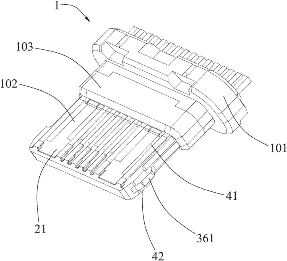
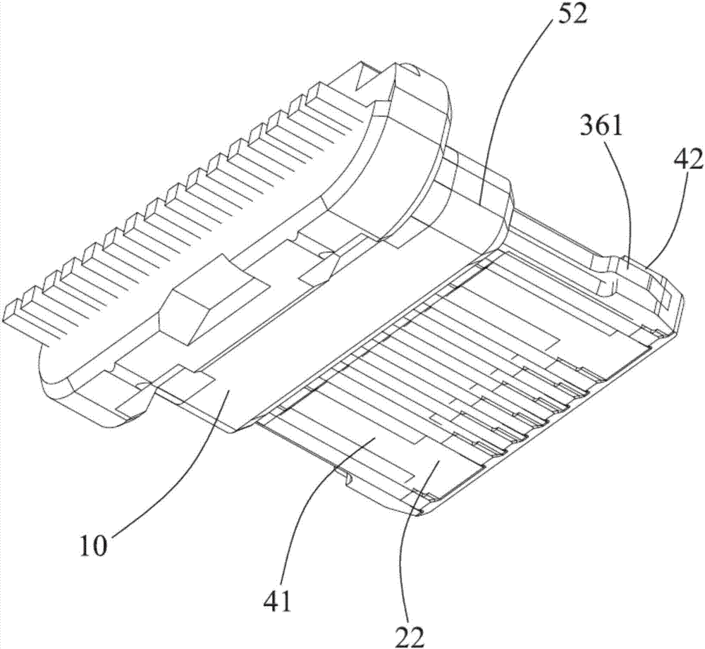
[0024] Such as Figures 1 to 5 As shown, it is an electrical connector according to the present invention, which includes a terminal module 1 , the terminal module includes an insulating body 10 , a first row of terminals 11 and a second row of terminals 12 arranged in a transverse direction. The insulating body 10 includes a base 101 , a tongue 102 located in front of the base 101 , and a step 103 connecting the base and the tongue 102 . The vertical thickness of the base portion 101 is greater than the vertical thickness of the step portion 102 , and the vertical thickness of the step portion 102 is greater than the vertical thickness of the tongue plate 103 .
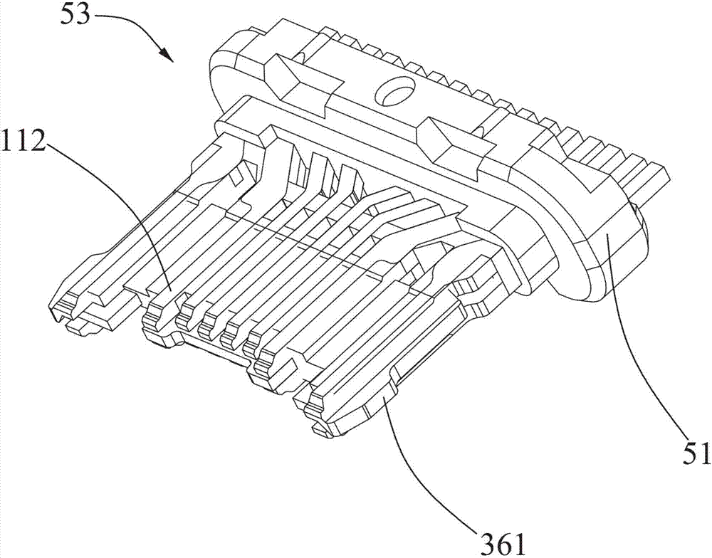
[0025] The first row of terminals 11 includes a first embedded portion 111 fixed in the base portion 101 , a first contact portion 112 extending forward from the first embedded portion 111 an...
PUM
 Abstract
Description
Claims
Application Information