
Insulation product having directional facing layer thereon and method of making the same

a technology of directional facing and directional layer, which is applied in the direction of heat-proofing, layered products, transportation and packaging, etc., can solve the problems of reducing the width of the vapor barrier, affecting the vapor barrier, so as to reduce the width and reduce the width

Inactive Publication Date: 2005-04-21
CERTAINTEED CORP
View PDF99 Cites 30 Cited by
  • Summary
  • Abstract
  • Description
  • Claims
  • Application Information

AI Technical Summary

Benefits of technology

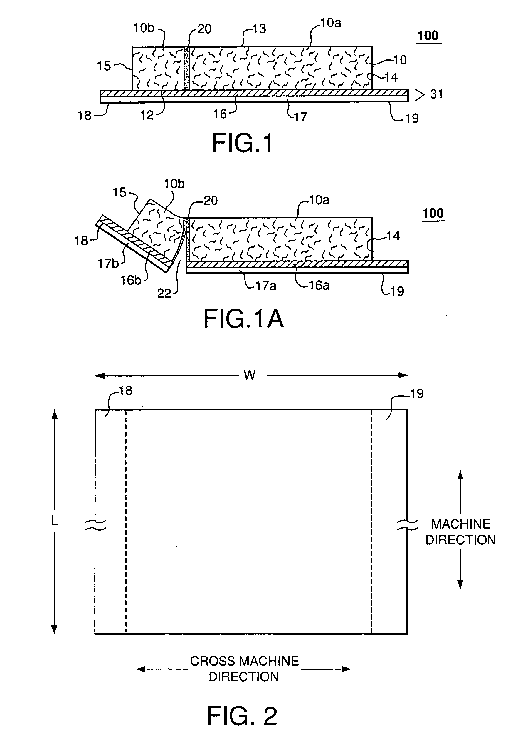
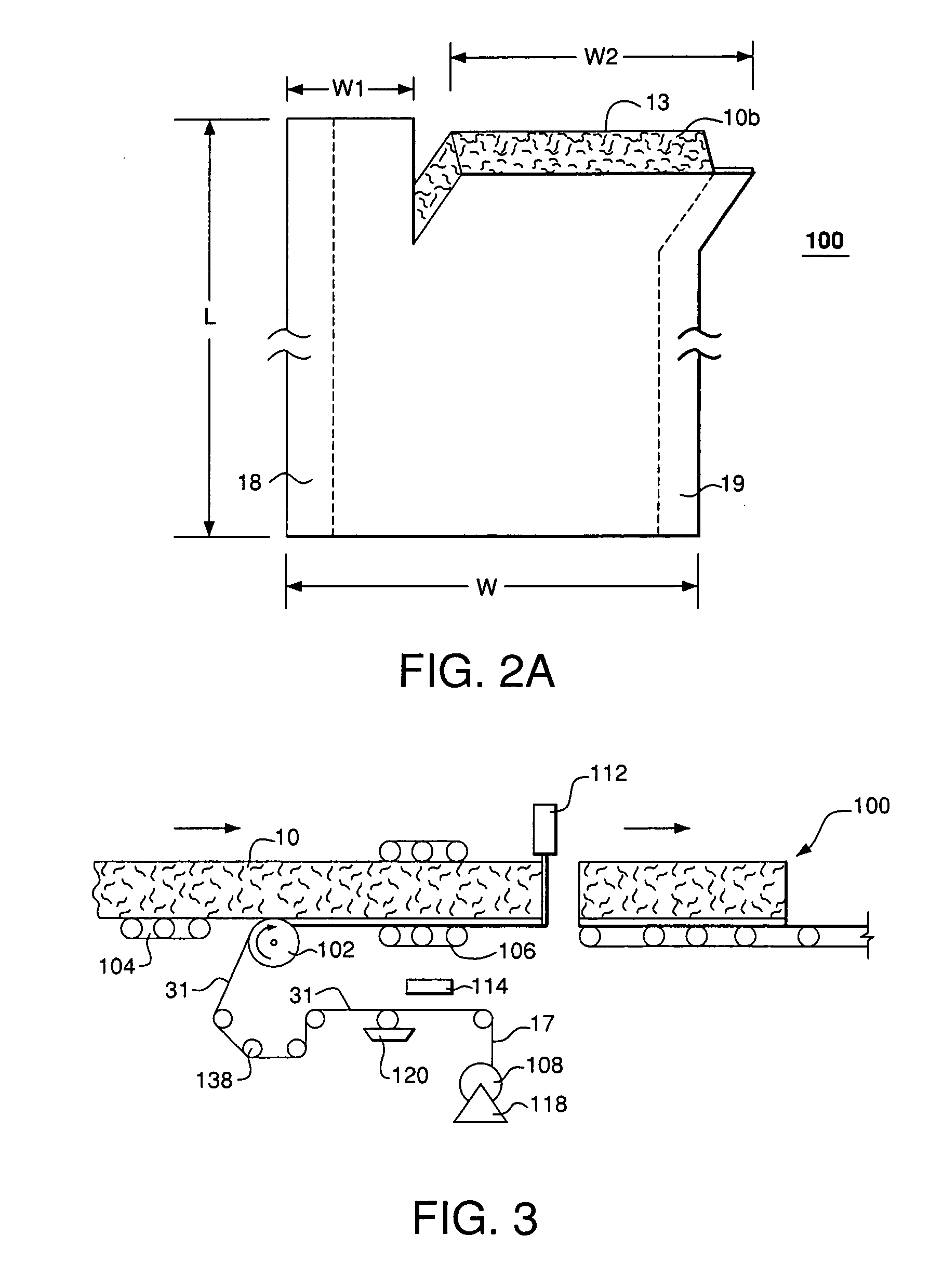
[0010] From the foregoing, a modular faced insulation product is provided that provides for user friendly field separation into smaller segments while not compromising the vapor retarder barrier thereon. In some embodiments, a facing layer having reduced width and / or paper weight but of sufficient cross machine direction tear strength may be achieved. The process of forming a faced insulation product is also simplified in that various facing layers each having different perforation locations are not required for different modular products and need not be stored and / or the step of perorating the facing layer can be eliminated or reduced. Cost saving attributable to materials and storage thereof may be realized.
[0012] A method of forming a reduced width insulation product from a master insulation product for installation in a structure is also provided comprising the following steps: (a) providing a master insulation product comprising an insulation mat comprising randomly oriented fibers, the mat having first and second major surfaces and a pair of side portions; and a facing layer comprising a cellulosic paper bonded to the insulation mat with a vapor retardant adhesive, the facing layer having a fiber orientation such that the facing layer has a ratio of machine direction tensile strength to cross machine direction tensile strength which permits the facing layer to be separated by hand along a substantially straight line selected in the machine direction, wherein the insulation mat includes a plurality of separable segments, the segments being coupled to each other along at least one plane oriented in the machine direction; and (b) separating the facing layer in the machine direction substantially along a plane from said at least one plane to remove at least one of the separable segments from the master insulation product, thereby providing a reduced width insulation product.

Problems solved by technology

This method of trimming the insulation batts at the job sight by cutting the batts to fit between the more closely spaced support members is time consuming, raises a significant risk or safety issue and relies heavily on the worker's skill to accurately trim the batt or panel.
Although Weinstein I provides a modular mat that can be separated into insulation mats of smaller widths, the use of a perforated facing layer raises several issues.
Further, it is believed that the perforations may provide breaches in the vapor barrier provided by the facing layer if the bonding agent does not fully or adequately fill the perforations.
These localized vapor barrier failures compromise the effectiveness of the insulation mat when the mat is used with, for example, support members spaced at standard widths, i.e., when the separable segments of the mat are not removed.

Method used


Image

  • Insulation product having directional facing layer thereon and method of making the same
  • Insulation product having directional facing layer thereon and method of making the same
  • Insulation product having directional facing layer thereon and method of making the same

Examples


Embodiment Construction

[0022] As used herein, the following terms are defined:

[0023]“Mat” means a fibrous material consisting of randomly oriented filaments, short fibers (with or without a carrier fabric), or swirled filaments held together with a binder, and are available in blankets of various thicknesses, widths, weights, and lengths. As used herein, “Insulation Mat” includes insulation boards, such as duct boards, insulation batts and acoustic insulation;

[0024]“Machine Direction” as used herein with respect to a layer means the direction in which the greater number of the fibers of a sheet of paper tend to be oriented as a result of the forward motion of the wire of the papermaking machine. The paper so produced is stronger in the machine direction, and also experiences less dimensional variation in the machine direction due to changes in humidity.

[0025]“Cross Machine Direction” with respect to a layer means the direction at right angles to the machine direction;

[0026]“Tensile Strength” means the...


PUM

PropertyMeasurementUnit
Ratioaaaaaaaaaa
Widthaaaaaaaaaa
Tensile strengthaaaaaaaaaa

Abstract

An insulation product is provided comprising an insulation mat comprising randomly oriented fibers. The mat has first and second major surfaces and a pair of side portions. A vapor retardant facing layer is bonded to at least one of the major surfaces of the mat. The facing layer has a fiber orientation such that the facing layer has a ratio of machine direction tensile strength to cross machine direction tensile strength which permits the facing layer to be separated by hand along a substantially straight line selected in the machine direction.

Description

CROSS-REFERENCE TO RELATED APPLICATIONS [0001] This application is a continuation-in-part of copending, commonly assigned patent applications: U.S. patent application Ser. No. 10 / 690,295, entitled “Separable Fibrous Insulation”, filed Oct. 21, 2003. This application is also related to the following copending, commonly assigned patent applications: U.S. Provisional Application No. XX / XXX,XXX [Attorney Docket No. D0932-00441], entitled “Segmented Band Joist Batts and Method of Manufacture”, filed Jan. 30, 2004; U.S. Provisional Application No. XX / XXX,XXX [Attorney Docket No. D0932-00442], entitled “Kit of Parts for Band Joist Insulation and Method of Manufacture”, filed Jan. 30, 2004; and U.S. Utility Patent Application No. XX / XXX,XXX [Attorney Docket No. D0932-00438], entitled “Method and Apparatus for Adhering Together Lanes of Compressible Products”, filed Feb. 11, 2004.FIELD OF THE INVENTION [0002] The present invention relates to insulation products and methods of making the same...

Claims


Application Information

Patent Timeline
IPC IPC(8): E04B1/76
CPCD04H13/002E04B2001/7695E04B1/767E04B1/7662B32B5/26Y10T428/249924
Inventor LEMBO, MICHAEL J.
Owner CERTAINTEED CORP
Learn More