Hydrodynamic force rotor type cavitator

A fluid dynamic, rotor-type technology, applied in fluid mixers, chemical instruments and methods, chemical/physical processes, etc., can solve problems such as liquid flow energy dissipation, improve quality, enhance chemical changes, and improve process efficiency Effect

Active Publication Date: 2017-07-07
顾履明
View PDF12 Cites 6 Cited by
  • Summary
  • Abstract
  • Description
  • Claims
  • Application Information

AI Technical Summary

Problems solved by technology

The disadvantage of this rotor type device is manifested in the energy dissipation of the liquid flow, which can be observed at high and low flow rates of the process liquid, at low flow rates a large number of bubbles appear in the annular chamber and the liquid is thrown out of the device, at larger Liquid may "run over" the cavitation barrier at flow rates with very low efficiency of process action

Method used


Image

  • Hydrodynamic force rotor type cavitator
  • Hydrodynamic force rotor type cavitator
  • Hydrodynamic force rotor type cavitator

Examples


Embodiment Construction

[0041] The principles and features of the present invention will be described below with reference to the accompanying drawings. The examples are only used to explain the present invention, but not to limit the scope of the present invention.

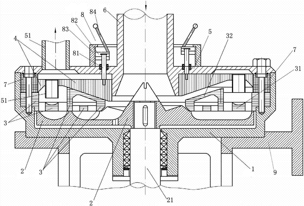
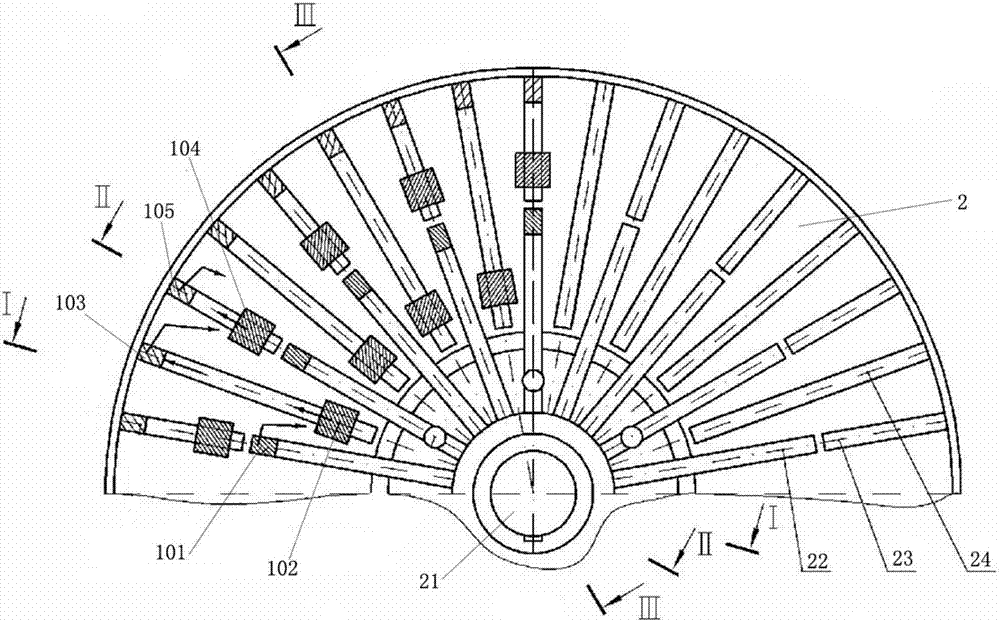
[0042] like Figure 1-Figure 9 As shown, a hydrodynamic rotor cavitator in this embodiment includes a body 1, a rotor 2, a stator 3, a panel 4 with a central hole, and a cover 5 with a central hole arranged coaxially in sequence. The body 1 is installed on the base 9; the inner shaft 21 vertically fixedly arranged at the center of the rotor 2 passes through the center of the body 1 and is connected with the body 1 through a bearing, and the inner shaft 21 is connected with the body 1 from the body 1 the inner shaft 21 is connected with the electric motor; the peripheral edge of the machine cover 5 is fixedly connected with the peripheral edge of the body 1; the peripheral edge of the stator 3 is crimped and fixed on the machine body Be...


PUM


Abstract

The invention relates to a hydrodynamic force rotor type cavitator. The hydrodynamic force rotor type cavitator comprises a machine body, a rotor, a stator, an embedded plate with a central hole and a machine cover which are coaxially arranged in turn, wherein a built-in shaft which is vertically fixed at the center of the rotor penetrates through the center of the machine body and is connected with the machine body through a bearing; the built-in shaft is in driving connection with a motor; a peripheral edge of the machine cover is fixedly connected with the peripheral edge of the machine body; the peripheral edge of the stator is fixedly pressed between the machine cover and the rotor; the embedded plate is moveably connected with the machine cover and is located between the machine cover and the stator; the embedded plate can move along an axial direction of the machine cover and a second-level cavitating chamber with adjustable volume is formed between the embedded plate and the stator; a first-level cavitating chamber is arranged in the stator; and the first-level cavitating chamber is communicated with a guiding pipe. In the hydrodynamic force rotor type cavitator provided by the invention, a plurality of cavitating barriers for performing liquid cavitating treatment are arranged between the stator and the rotor, so that the technical efficiency of the cavitation effect is obviously increased, the chemical change of the liquid is intensified, the high-degree microorganism disinfection of the liquid is guaranteed and the quality of microcosmic homogeneous emulsion and suspension is promoted.

Description

technical field [0001] The invention relates to a device for generating cavitation in conveying liquid medium, in particular to a hydrodynamic rotor type cavitator. Background technique [0002] Most of the known hydrodynamic rotor equipment structures (according to the centrifugal pump type) for generating cavitation include a body with a short pipe at the inlet and outlet, a stator and a rotatable rotor arranged concentrically in the body. The continuous medium in the conveying liquid is broken and cavitation occurs in the blocked flow channel of the stator and rotor. [0003] The known rotor-type equipment comprises a body with an annular chamber and a slotted stator arranged therein and a rotor with inner and outer working impellers having inlet and outlet passages communicating with the annular chamber, while the inlet flow of one of the working impellers The channel communicates with the annular chamber. The disadvantage of this rotor type device is that it works uns...

Claims


Application Information

Patent Timeline
Patent Type & Authority Applications(China)
IPC IPC(8): B01F5/00B01F5/10B01F3/04
CPCB01F23/23B01F23/2366B01F23/2373B01F25/10B01F25/50B01F2101/2204
Inventor 顾履明亚历山大·吉里拉维奇·库罗奇金许小宁安东·亚历山大维奇·库罗奇金
Owner 顾履明
Why Eureka
Try Eureka