Material stirring device for producing brake blocks

A stirring device and brake pad technology, which is applied in the field of ingredients stirring device for brake pad production, can solve the problems of uneven mixing and low mixing efficiency, and achieve the effect of convenient and effective stirring

Inactive Publication Date: 2017-07-07
来安县华鹏摩擦材料厂
View PDF4 Cites 7 Cited by
  • Summary
  • Abstract
  • Description
  • Claims
  • Application Information

AI Technical Summary

Problems solved by technology

[0006] In order to overcome the shortcomings of low stirring and mixing efficiency and uneven mixing of a large number of raw materials in the prior art, the technical problem to be solved by the present invention is to provide an ingredient for brake pad production that can stir and mix a large amount of raw materials evenly and quickly Stirring device

Method used


Image

  • Material stirring device for producing brake blocks
  • Material stirring device for producing brake blocks
  • Material stirring device for producing brake blocks

Examples


Embodiment 1

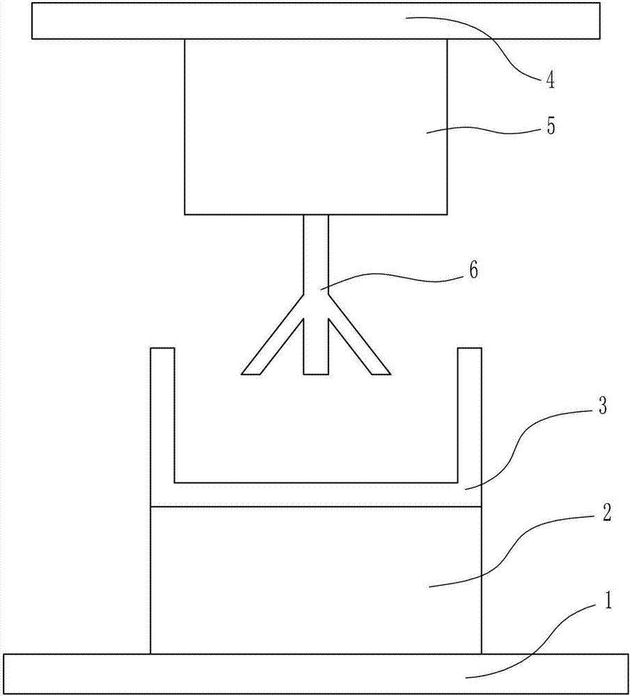
[0040] An ingredient mixing device for brake pad production, such as Figure 1-7 As shown, it includes a bottom plate 1, a swing device 2, a stirring box 3, a top plate 4, a lifting device 5 and a stirring rod 6, the top of the bottom plate 1 is connected with a swing device 2, the top of the swing device 2 is connected with a stirring box 3, and the stirring box The upper side of 3 is provided with top plate 4, and the bottom of top plate 4 is connected with elevating device 5, and the bottom of elevating device 5 is connected with stirring rod 6, and stirring rod 6 is positioned in mixing box 3.

Embodiment 2

[0042] An ingredient mixing device for brake pad production, such as Figure 1-7 As shown, it includes a bottom plate 1, a swing device 2, a stirring box 3, a top plate 4, a lifting device 5 and a stirring rod 6, the top of the bottom plate 1 is connected with a swing device 2, the top of the swing device 2 is connected with a stirring box 3, and the stirring box The upper side of 3 is provided with top plate 4, and the bottom of top plate 4 is connected with elevating device 5, and the bottom of elevating device 5 is connected with stirring rod 6, and stirring rod 6 is positioned in mixing box 3.

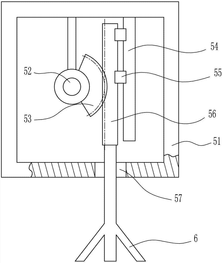
[0043] Lifting device 5 comprises installation box 51, first motor 52, sector gear 53, first slide rail 54, first slide block 55 and first rack 56, and the bottom of top plate 4 is connected with installation box 51, and inside installation box 51 The top wall on the left side is connected with a first motor 52, the output shaft of the first motor 52 is connected with a sector gear...

Embodiment 3

[0045] An ingredient mixing device for brake pad production, such as Figure 1-7 As shown, it includes a bottom plate 1, a swing device 2, a stirring box 3, a top plate 4, a lifting device 5 and a stirring rod 6, the top of the bottom plate 1 is connected with a swing device 2, the top of the swing device 2 is connected with a stirring box 3, and the stirring box The upper side of 3 is provided with top plate 4, and the bottom of top plate 4 is connected with elevating device 5, and the bottom of elevating device 5 is connected with stirring rod 6, and stirring rod 6 is positioned in mixing box 3.

[0046] Lifting device 5 comprises installation box 51, first motor 52, sector gear 53, first slide rail 54, first slide block 55 and first rack 56, and the bottom of top plate 4 is connected with installation box 51, and inside installation box 51 The top wall on the left side is connected with a first motor 52, the output shaft of the first motor 52 is connected with a sector gear...


PUM


Abstract

The invention relates to a material stirring device, and in particular relates to a material stirring device for producing brake blocks. The technical problem to be solved in the invention is to provide a material stirring device for producing brake blocks, which can uniformly stir and mix a large number of raw materials at a high speed. In order to solve the technical problem, the invention provides such a material stirring device for producing brake blocks. The material stirring device comprises a bottom plate, a swing device, a stirring box, a top plate, a lifting device and a stirring rod, wherein the swing device is connected to the top of the bottom plate, the stirring box is connected to the top of the swing device, the top plate is arranged on the upper side of the stirring box, the lifting device is connected to the bottom of the top plate, the stirring rod is connected to the bottom of the lifting device, and the stirring rod is located in the stirring box. The material stirring device is provided with the lifting device to drive the stirring rod to move up and down so as to stir the raw materials in the stirring box, and thus the effect of stirring the raw materials quickly and effectively is realized.

Description

technical field [0001] The invention relates to a batching stirring device, in particular to a batching stirring device for brake pad production. Background technique [0002] Brake pads are also called brake pads. In the braking system of a car, the brake pads are the most critical safety parts. The brake pads play a decisive role in the quality of all braking effects, so good brake pads are the protectors of people and cars. [0003] In the production process of the current brake pads, batching is required. The batching is to stir and mix a large number of raw materials. The existing large amount of raw materials are directly mixed, so the mixing efficiency is low, and the mixing is uneven, which affects the brake pads. production efficiency. [0004] Therefore, there is an urgent need to develop an ingredient mixing device for brake pad production that can uniformly and quickly mix a large amount of raw materials to solve the shortcomings of low mixing efficiency and un...

Claims


Application Information

Patent Timeline
Patent Type & Authority Applications(China)
IPC IPC(8): B01F11/00
CPCB01F31/00B01F31/60B01F31/70B01F31/441
Inventor 华鹏
Owner 来安县华鹏摩擦材料厂
Why Eureka
Try Eureka