Clip body manufacturing method of hairpin, clip body and hairpin composed of two clip bodies

A manufacturing method and clip body technology, which can be applied to curling or perming devices, hairdressing equipment, applications, etc., and can solve the problems of injury risk, unsatisfactory clip stability, and increased cost.

Active Publication Date: 2019-03-29
徐士凌
View PDF4 Cites 0 Cited by
  • Summary
  • Abstract
  • Description
  • Claims
  • Application Information

AI Technical Summary

Problems solved by technology

[0006] However, the toothed needle 123' of the aforementioned structure only penetrates the plug hair 4' straightly, and the toothed needle 123' cannot hook the hair 4' by itself, which still causes unsatisfactory hair clip stability, and the material of the toothed needle 123' is relatively hard. Its tip is located at the topmost position, causing the risk of injury when the human skin touches the tip of the toothed needle 123'
[0007] another example Figure 10 As shown, in the conventional hair clip, in order to improve the anti-slip and comfort, the inner surface 122' of the hard jaw 121' is adhesively bonded with a soft anti-slip sheet 124', and the anti-slip sheet 124' is attached to the hair 4' In order to improve the anti-slip effect, however, the above-mentioned structure must be additionally equipped with an anti-slip sheet 124', which has the disadvantage of increased cost, and the anti-slip sheet 124' will easily fall off due to the deterioration of the glue after the hairpin is used for a period of time

Method used


Image

  • Clip body manufacturing method of hairpin, clip body and hairpin composed of two clip bodies
  • Clip body manufacturing method of hairpin, clip body and hairpin composed of two clip bodies
  • Clip body manufacturing method of hairpin, clip body and hairpin composed of two clip bodies

Examples


no. 1 example

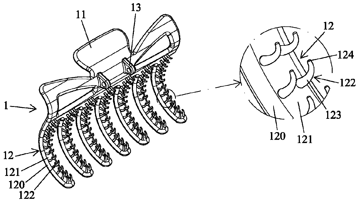
[0046] In the following embodiments, similar functional components of the present invention are represented by the same figure number, please refer to figure 1 In the first embodiment of the present invention, the clip body 1 of the hairpin is integrally molded from plastic, with a pressing portion 11 at one end and a clamping portion 12 at the other end, with jaws 120 arranged below the clamping portion 12, and the clip body 1 There is a pivot joint 13 on the inner side, and the clamping part 12 has an inner surface 121, and a plurality of tooth hooks 122 are arranged in a direction perpendicular to the corresponding inner surface 121. The connected straight part 123 is substantially straight, and the top end of the straight part 123 has a hook part 124 bent corresponding to the straight part 123 .

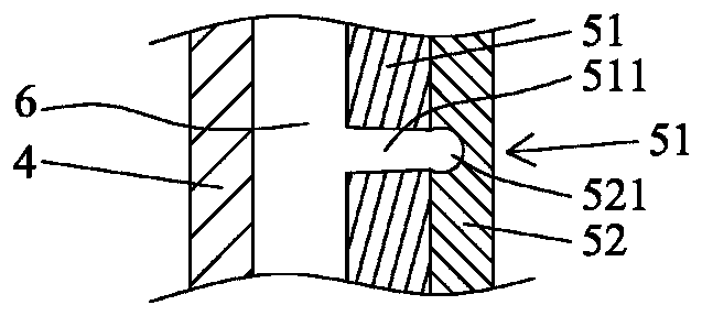
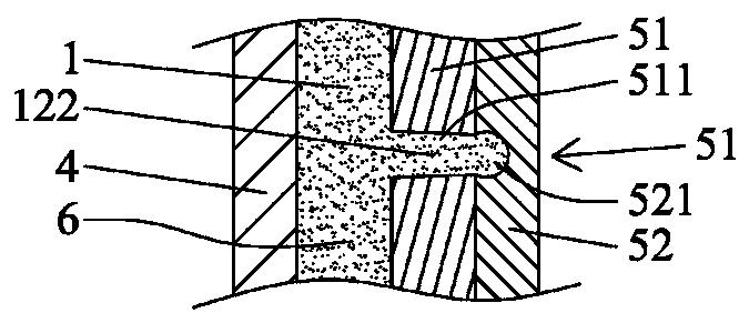
[0047] see figure 1 and Figure 2A to Figure 2E ,in Figure 2A to Figure 2E It mainly shows the position of the molded clip body 1 corresponding to the tooth hook 122. The m...


PUM

PropertyMeasurementUnit
Shore hardnessaaaaaaaaaa
diameteraaaaaaaaaa
hardnessaaaaaaaaaa

Abstract

The invention provides a clip body manufacture method of a clip, a clip body of the clip and the clip composed of the two clip bodies. The clip body manufacture method includes the following steps that S1, a fixed mold plate and a movable mold plate are manufactured, at least one mold cavity capable of forming the corresponding clip body is formed after the fixed mold plate and the movable mold plate are assembled, a first mold plate is arranged on the side, corresponding to the fixed mold plate, on the inner side of the movable mold plate, and the first mold plate is provided with linear channels communicating with the mold cavities; a second mold plate is fixedly arranged on the outer side of the first mold plate, and grooves with the diameter larger than that of the outer side ends of the channels are formed in the positions, corresponding to the channels, of the second mold plate; S2, a fixed mold and a movable mold are assembled, plastic is ejected out so that the mold cavities, the channels and the grooves can be full filled with the plastic; S3, the movable mold plate is made to be separated from the fixed mold plate, and the clip bodies can be attached to the movable mold plate; S4, the clip bodies are ejected and supported to move by a set distance relative to the movable mold plate, and the plastic at the positions of the corresponding grooves can be pulled to be thin and long through cooperation with the ductility and malleability of the plastic; and S5, after the step S4 is executed for a set period of time, the clip bodies are ejected and supported to be completely separated from the movable mold plate; and by means of the clip body manufacture method, the clip body and the clip, the non-slip effect of the clip can be improved.

Description

technical field [0001] The present invention relates to a method for manufacturing a clip body of a hair clip and the clip body and a hair clip composed of two clip bodies, and mainly refers to a clip body and a hair clip that can improve the anti-slip effect. Background technique [0002] Conventional hair clips generally have a clip body that can be used for clipping hair. The clip body can be two oppositely arranged, and the two clip bodies can be of the same or different shapes, and the two clip bodies can be closed to clip the hair. [0003] Such as Figure 7 , 8 Shown is a conventional hairpin structure, with two clips 1', a pivot 2', and an elastic component 3'. The two clips 1' are integrally formed of hard plastic, and its hardness is about 93A~105A in Shore hardness. , and is a relative shape, the upper part has a pressing part 11', the lower part has a clamping part 12', and the center of the inner side is provided with a pivot part 13', the clamping part 12' has...

Claims


Application Information

Patent Timeline
Patent Type & Authority Patents(China)
IPC IPC(8): B29C45/00B29C45/26A45D8/14
CPCA45D8/14B29C45/0055B29C45/2602
Inventor 徐士凌
Owner 徐士凌
Why Eureka
Try Eureka