
Plastic packaging bag clean film processing device

A processing device and packaging bag technology, applied in water supply devices, transportation and packaging, thin material handling, etc., can solve the problems of film deformation, small thickness, poor thermal stability, etc., and achieve the effect of smooth unwinding

Pending Publication Date: 2022-07-29
安徽九润纸塑包装有限公司
View PDF0 Cites 0 Cited by
  • Summary
  • Abstract
  • Description
  • Claims
  • Application Information

AI Technical Summary

Problems solved by technology

However, the disinfection method disclosed in the prior art is to sterilize the produced inner mold roll. Since the clean film is in a winding state, the film inside the roll material cannot be conveniently sterilized.
[0004] Specifically, in the process of production and processing, most of the conveying devices for conveying inner molds disclosed in the prior art adopt horizontal conveying, which cannot be effectively sterilized during the conveying process. In the horizontal state, a large number of The liquefied alcohol droplets adhere to the film and follow the transmission of the film into the clean area. The alcohol droplets cannot be dried quickly, so after the alcohol enters the clean area, it is necessary to perform secondary treatment on the alcohol attached to the film. During the work process, in order to To improve drying efficiency, warm air drying is often used. However, due to the small thickness of the inner mold and poor thermal stability, the film is often deformed during the warm air drying process because the temperature and wind speed of the warm air are not controlled, especially fine Deformation, resulting in poor smoothness of the inner mold side of the entire plastic film after subsequent heat pressing on the outer mold

Method used


Image

  • Plastic packaging bag clean film processing device
  • Plastic packaging bag clean film processing device
  • Plastic packaging bag clean film processing device

Examples


Embodiment 1

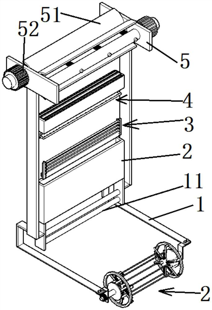
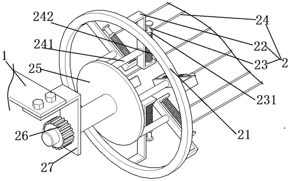
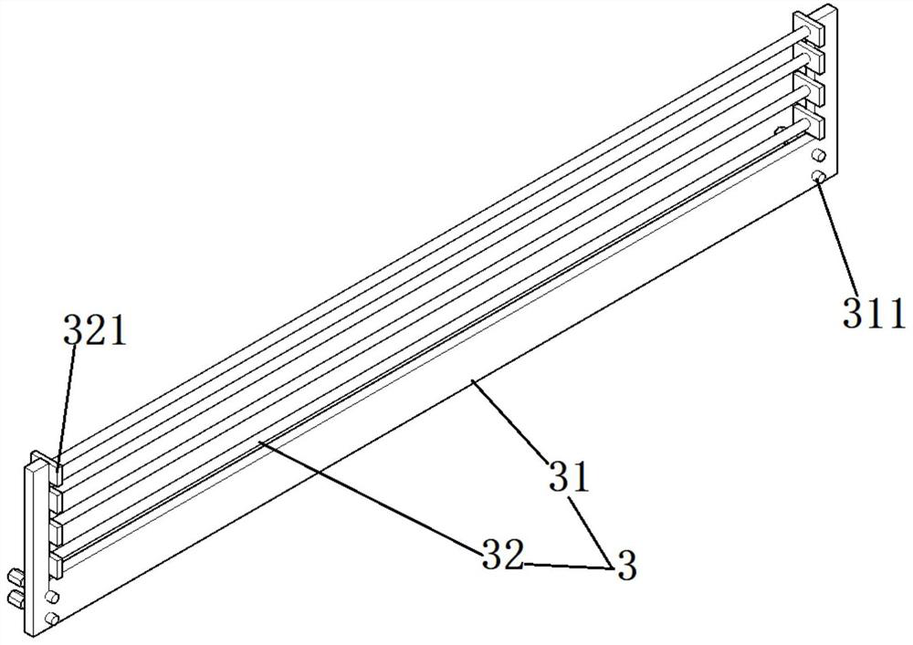
[0045] like Figure 1-8 As shown, a clean film processing device for plastic packaging bags includes bottom frame rods 1 arranged at intervals in the front and rear, and an elastic feeding mechanism 2 is assembled and connected between the outer ends of the bottom frame rods 1;

[0046] Specifically, the elastic feeding mechanism 2 realizes the winding of the film for winding. The specific structure of the elastic feeding mechanism 2 is as follows:

[0047]The elastic feeding mechanism 2 includes folded end frames 27 (L-shaped steel plates) arranged at intervals in the front and rear, and the folded end frames 27 are fixedly assembled on the bottom of the bottom frame rod 1 . Specifically, it is assembled by bolts. The folded end frame 27 is provided with end seat portions, and elastic feeding components are rotatably connected between the end seat portions.

[0048] The specific structure of the elastic feeding part is as follows:

[0049] The elastic feeding component in...

Embodiment 2

[0055] like Figure 1-8 As shown, in this embodiment, on the basis of the structure of Embodiment 1, the inner end of the bottom frame rod 1 is fixedly connected with the longitudinal frame 6 facing upward.

[0056] A clean film sterilization mechanism is assembled and connected between the lower ends of the longitudinal frame 6; specifically, the clean film sterilization mechanism includes a longitudinally arranged sterilization box 2, and the bottom and bottom of the sterilization box 2 are provided with material holes, and the longitudinal frame 6 A bottom vertical plate is fixedly connected with the bottom of the bottom vertical plate, and a limit material rod 11 arranged at an upper and lower interval is fixedly connected between the bottom vertical plates. After the unrolled film is staggered and interspersed between the limit material rods 11, it enters the sterilization box 2 for longitudinal transmission, and is sterilized during the longitudinal transmission.

[005...

Embodiment 3

[0062] In this embodiment, on the basis of the structure of Embodiment 2, in order to realize the vertical pulling and conveying of the film, specifically, because the alcohol disinfectant is attached to the film, its lubricity is increased, and the transmission and conveying device cannot be smoothly conveyed. The conveying process Slip is prone to occur in the film, resulting in film breakage.

[0063] The specific structure of the arc plate pulling assembly is as follows:

[0064] The arc-shaped plate pulling assembly includes a horizontal base plate 5 that is fixedly connected to the top of the longitudinal frame 6, respectively, and two drive rollers 53 spaced left and right are rotatably connected to the horizontal base plate 5, and the drive rollers 53 are assembled and connected respectively. The cooperating bearing plate 51 (the heart-shaped angle of the bearing plate 51 is 180 degrees), the bearing plate 51 is assembled and connected to the driving roller 53 through ...


PUM


Abstract

The invention discloses a plastic packaging bag clean film processing device which comprises bottom rack rods arranged front and back at intervals, and an elastic feeding mechanism is assembled and connected between the outer ends of the bottom rack rods. The inner ends of the bottom rack rods face upwards and are fixedly connected with longitudinal racks; a clean film disinfection mechanism is assembled and connected between the lower ends of the longitudinal racks; the clean film disinfection mechanism comprises a disinfection box, and an ultraviolet lamp disinfection component is assembled and connected in the disinfection box; the clean film disinfection mechanism further comprises an alcohol mist disinfection component, the alcohol mist disinfection component comprises a disinfection pipe, the disinfection pipe is communicated with a plurality of disinfection nozzles, the disinfection pipe is communicated with an inlet pipe, and the inlet pipe penetrates through the disinfection box. According to the design, the thin film is conveyed in a vertical feeding state, disinfection alcohol mist is sprayed, liquefied alcohol water drops continuously drop on the thin film and are air-dried in the conveying process, and the technical defects that in a horizontal conveying mode disclosed in the prior art, alcohol liquid drops are attached to the thin film and cannot be rapidly separated from the thin film are overcome.

Description

technical field [0001] The invention belongs to the technical field of plastic packaging bag processing, and in particular relates to a cleaning film processing device for plastic packaging bags. Background technique [0002] A plastic packaging bag is a packaging bag used for processing and packaging food, which includes an inner mold that is in direct contact with the food and an outer mold that is hot-pressed on the inner mold. The inner mold is designed with a clean film. During the production process, the inner mold needs to be disinfected. [0003] Specifically, the sterilized inner membrane is compounded with cleanliness and enters the clean area for processing. However, the sterilization method disclosed in the prior art is to sterilize the produced inner mold roll. Since the clean film is in a rolled state, the film inside the roll cannot be easily sterilized. [0004] Specifically, in the production and processing process, most of the conveying devices for convey...

Claims


Application Information

Patent Timeline
IPC IPC(8): B65H23/035B65H16/06B65H18/02B65H18/10B65H75/14B65H75/18A61L2/10A61L2/18A61L2/26
CPCB65H16/06B65H18/028B65H18/10B65H23/035B65H75/14B65H75/18A61L2/26A61L2/10A61L2/18B65H2701/1133B65H2701/191
Inventor 龙海苗管春霞龙海千龙清兵许宜
Owner 安徽九润纸塑包装有限公司
Learn More