Foldable trolley
A trolley and booster technology, applied in trolleys, multi-axle trolleys, motor vehicles, etc., can solve problems such as noise, heavy trunks, and no other functions.
- Summary
- Abstract
- Description
- Claims
- Application Information
AI Technical Summary
Problems solved by technology
Method used
Image
Examples
Embodiment 1
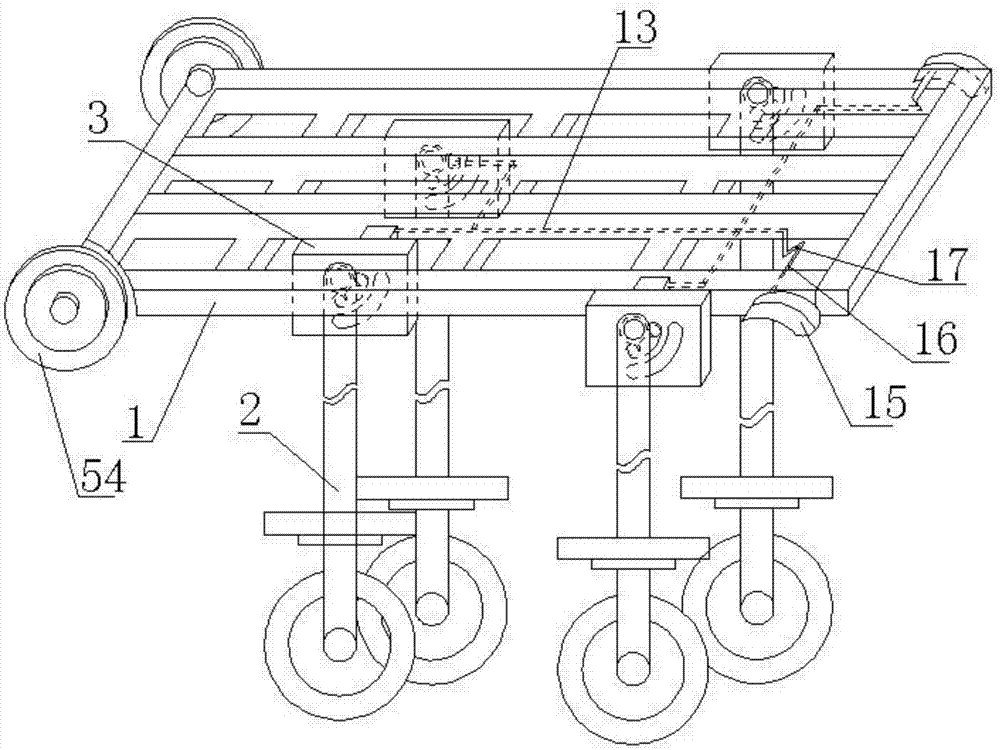
[0041] Such as figure 1 As shown, in order to achieve the purpose of directly pushing items to the car trunk or easily pulling them out from the car trunk, this embodiment provides a foldable trolley, including a support platform 1 and a support installed at the bottom of the support platform 1 Leg 2, the top section of the supporting leg 2 is movably connected with the mounting block 3 installed at the bottom of the supporting platform 1 .
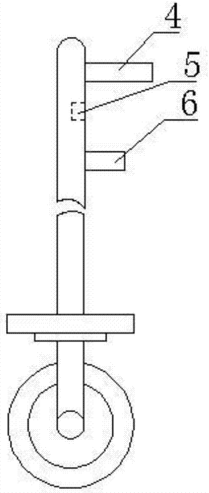
[0042] pass figure 2 It can be seen that a fixed pin 4 and a limiting hole 5 are sequentially arranged on the inner surface of the top section of the supporting leg 2 from top to bottom, and image 3 The shown mounting block 3 is provided with a fixing hole 7 for inserting the fixing pin 4, so that the supporting leg 2 can rotate around the fixing pin 4 as a rotating shaft or rotate around the fixing hole 7 with the fixing pin 4, for example, it can Bearings are installed in the fixing holes 7, and then connected with the fixing pins 4...
Embodiment 2
[0045] In order to facilitate a better understanding that the aforementioned foldable trolley can be folded by retracting the supporting legs 2, this embodiment provides Figure 4 The shown self-resetting limit ejector mechanism includes a limit ejector pin 9, a return spring 10 with one end clamp at the tail end of the limit ejector pin 9, and a return spring 10 whose two ends are fixed on the inner side of the installation block 3 through connecting round pipes 11. The spring supporting member 12 and the drawing member 13 fixedly connected with the tail end of the limit push pin 9 pass through the perforation on the return spring supporting member 12 .
[0046] A limit tube 14 is arranged on the side of the tail end of the return spring support member 12 facing the limit push pin 9 to be sleeved on the return spring 10 to ensure that the return spring 10 is compressed after the limit push pin 9 is pulled out. In the process or in the process of the reset spring 10 pressing t...
Embodiment 3
[0054] and Image 6 A self-resetting limit pin ejector mechanism of another structure is provided, including a housing 19, a ejector pin 20 that can pass through the lower positioning hole 8, a compression spring 21 and a booster assembly, a ejector 22 and a ejector rod 23; wherein, the ejector pin 20 and the compression spring 21 are installed in the blind hole 24 on one side of the housing 19, and the compression spring 21 is placed between the bottom of the blind hole 24 and the ejector pin tail end 25 of the ejector pin 20, The front end of the ejector pin 20 extends outside the blind hole 24; Figure 7 It can be seen that an inclined boosting surface 26 is arranged on the boosting side 30 parallel to the jacking pin 20 of the jacking pin tail end 25, and the tilting boosting surface 26 is from the front end of the jacking pin tail end 25 to the bottom of the jacking pin tail end 25. The direction of the rear end is inclined, and the inclined pushing surface 26 is arrange...
PUM
 Abstract
Description
Claims
Application Information
 - R&D
- Intellectual Property
- Life Sciences
- Materials
- Tech Scout
- Unparalleled Data Quality
- Higher Quality Content
- 60% Fewer Hallucinations
Browse by: Latest US Patents, China's latest patents, Technical Efficacy Thesaurus, Application Domain, Technology Topic, Popular Technical Reports.
© 2025 PatSnap. All rights reserved.Legal|Privacy policy|Modern Slavery Act Transparency Statement|Sitemap|About US| Contact US: help@patsnap.com


