
Looper thread hooking mechanism and fork needle forking mechanism for hose reel foot machine

A technology of roller foot machine and fork needle, which is applied in the direction of sewing machine collar mechanism, sewing machine needle seat, sewing machine components, etc., and can solve the problem of complex structure of looper hook mechanism and fork needle cross mechanism, which are prone to failure and cannot To meet the production requirements and other issues, to achieve the effect of improving cross-line efficiency, improving hook-line efficiency, and reducing failures

Active Publication Date: 2017-07-07
陈树滔
View PDF14 Cites 0 Cited by
  • Summary
  • Abstract
  • Description
  • Claims
  • Application Information

AI Technical Summary

Problems solved by technology

[0003] At present, the structure of the looper hooking mechanism and the fork needle hooking mechanism of the existing roller foot machine is too complicated, and it is prone to failure during use
Therefore, due to the unreasonable structure of the looper hooking mechanism and the fork needle hooking mechanism of the existing wheel foot machine, it still cannot meet the production requirements. For this, it is necessary to improve the wheel foot machine

Method used


Image

  • Looper thread hooking mechanism and fork needle forking mechanism for hose reel foot machine
  • Looper thread hooking mechanism and fork needle forking mechanism for hose reel foot machine

Examples


Embodiment Construction

[0036] In order for those skilled in the art to better understand the technical solutions provided by the present invention, the following will be described in conjunction with specific embodiments.

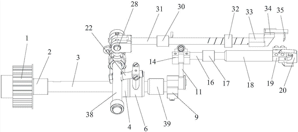
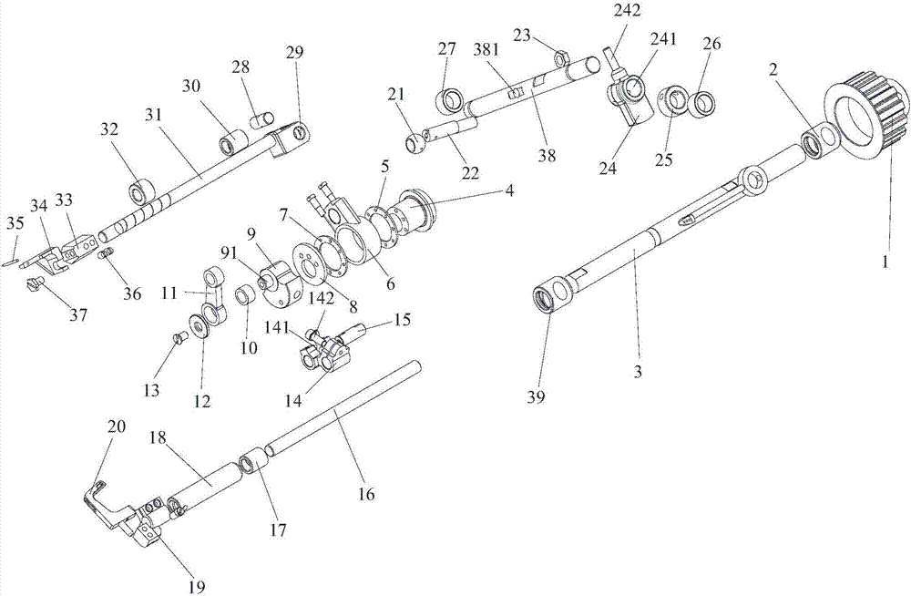
[0037] See Figure 1-Figure 2 , figure 1 It is a schematic diagram of the overall structure of the looper hooking mechanism and the fork needle hooking mechanism of the wheel foot machine in the embodiment of the present invention; figure 2 It is a schematic diagram of the exploded structure of the looper thread hooking mechanism and the fork needle thread hooking mechanism in the embodiment of the present invention.

[0038] The embodiment of the present invention provides the looper thread hooking mechanism and the needle thread crossing mechanism of the wheel hoist machine in the embodiment of the present invention, including the looper thread hooking mechanism and the needle thread crossing mechanism.

[0039] The looper thread hooking mechanism and the fork thread crossin...


PUM


Abstract

The invention relates to a looper thread hooking mechanism and a fork needle forking mechanism for a hose reel foot machine. A synchronizing wheel drives a lower shaft to rotate and the lower shaft drives a looper cam to rotate, and the looper cam drives a looper shaft to move from side to side through a looper connecting rod and a looper crank, so that a looper clamp and the looper move from side to side. The synchronizing wheel drives the lower shaft to rotate and the lower shaft drives a fork needle eccentric wheel to rotate, and the fork needle eccentric wheel drives a fork needle shaft to move from side to side along the direction perpendicular to the axis of the fork needle shaft through a fork needle connecting rod and a fork needle bolt; a fork needle rod and the fork needle shaft are vertically connected with a fork needle pin through a fork needle crank, so that the fork needle shaft drives the fork needle rod to move back and forth along the axis direction of the fork needle rod, and thus a fork needle clamp and the fork needle move back and forth. Compared with the prior art, the looper thread hooking mechanism and fork needle forking mechanism for the hose reel foot machine have the advantages that the hooker hooking and fork needle forking processes become smooth, the occurrence of fault is reduced, and the looper hooking and fork needle forking efficiency is improved.

Description

technical field [0001] The invention relates to the field of garment machinery, and more precisely refers to a looper thread hooking mechanism and a fork needle thread hooking mechanism of a wheel machine. Background technique [0002] Nowadays, with the development of the clothing industry, people are increasingly pursuing the beauty and diversity of clothing. In addition to the requirements for the style of the clothing itself, there are also requirements for the details of the corners of the clothing. Sewing is performed to enhance the quality, taste and added value of garments. In the present application, clothing has a broad meaning and is not limited to clothes and trousers, but also includes footwear, hats, gloves, trousers, denim trousers, work clothes and casual clothes. [0003] At present, the structure of the looper thread hooking mechanism and the fork needle thread crossing mechanism of the existing roller foot machine is too complicated, and it is prone to fa...

Claims


Application Information

Patent Timeline
Patent Type & Authority Applications(China)
IPC IPC(8): D05B57/00D05B57/30D05B55/14
CPCD05B55/14D05B57/00D05B57/30
Inventor 陈树滔
Owner 陈树滔
Learn More