Conical volute chamber cyclone shaft flood discharging tunnel system

A technology of flood discharge tunnel and vortex chamber, which is applied in the field of flood discharge technology and energy dissipation, can solve the problems of increasing the height of the vortex chamber section, increasing the pressure of the bottom plate, the damage of the bottom plate, and falling to the bottom of the shaft, so as to reduce the design height and reduce the Increase the amount of excavation and improve the effect of protecting the floor

Active Publication Date: 2017-07-07
SICHUAN UNIV
View PDF2 Cites 15 Cited by
  • Summary
  • Abstract
  • Description
  • Claims
  • Application Information

AI Technical Summary

Problems solved by technology

[0003] However, since the water flow entering the vortex chamber in the upper flat section has a certain width (that is, the normal water depth of the inner wall of the vortex chamber), the closer the water body is to the center of the vortex chamber, the easier it is for the water body to break free from the constraints of the mainstream, and then directly fall to the bottom of the shaft.
This is because the circumferential velocity of part of the water body in the direction of the free surface of the water flow gradually decreases during the vertical discharge process, so that it is not enough to support the bot

Method used


Image

  • Conical volute chamber cyclone shaft flood discharging tunnel system
  • Conical volute chamber cyclone shaft flood discharging tunnel system
  • Conical volute chamber cyclone shaft flood discharging tunnel system

Examples


Embodiment 1

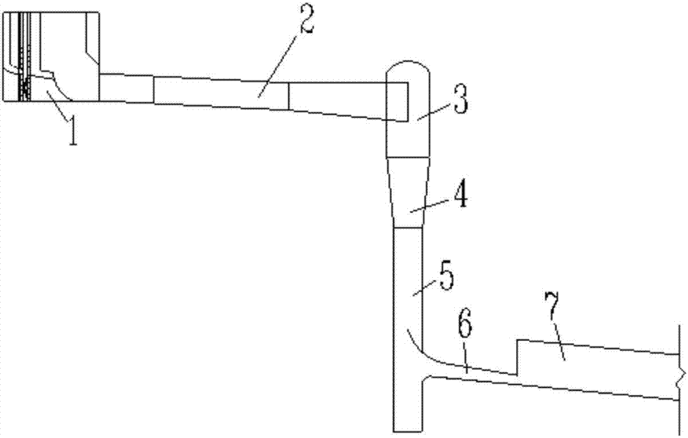
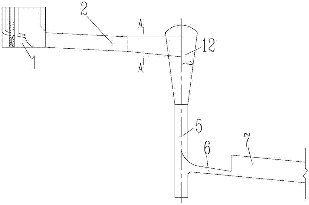
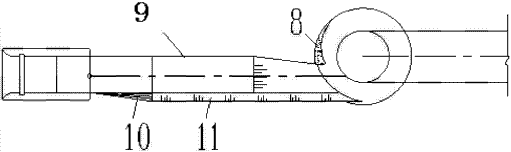
[0021] The conical vortex chamber swirl shaft spillway system described in this embodiment has a structure as attached figure 2 , attached image 3 And attached Figure 4 As shown, it is composed of lock chamber 1 (inlet), upper flat section 2, vortex chamber 3, contraction section 4, vertical shaft straight section 5, outlet pressure slope section 6 and subsequent lower flat discharge section 7. The vortex chamber is Conical structure vortex chamber with the same shrinkage slope ratio as the lower constriction section, and continuous and smooth connection with the constriction section, the side wall tangentially connecting the upper flat section with the vortex chamber is an inclined side with the same shrinkage slope ratio as the vortex chamber wall. A twisted surface 10 extending along the direction of water flow is arranged between the lock chamber and the inclined side wall of the upper flat section. The smooth transition is connected to the inclined side wall of the ...


PUM


Abstract

The invention discloses a cyclone shaft flood discharging tunnel system. The system comprises a gate chamber, an upper flat section, a volute chamber, a shrinkage section, a shaft straight section, an outlet pressure slope section, and a lower flat sluicing section on the back side of the outlet pressure slope section; the volute chamber is of a conical structure having the same one shrinkage slope rate with a lower shrinkage section and smoothly joined with the shrinkage section; and an edge wall, tangential to and joined with the volute chamber, of the upper flat section is an inclined edge wall having the same shrinkage slope rate with the volute chamber. The conical volute chamber cyclone shaft flood discharging tunnel can reduce the possibility of water directly falling to the bottom of a shaft at the tail end of the shrinkage section, improves the energy dissipation effect, meanwhile, reduces the height requirement of the volute chamber, reduces the excavation quantity, and saves the engineering investment.

Description

technical field [0001] The invention belongs to the technical field of flood discharge and energy dissipation in water conservancy and hydropower projects, and in particular relates to a swirl shaft flood discharge tunnel system. Background technique [0002] Due to its low construction difficulty, flexible layout and outstanding energy dissipation effect, the swirl shaft flood discharge tunnel has attracted more and more attention from the field of water conservancy and hydropower engineering, especially as my country is currently in the stage of blowout development of hydropower construction. Many high-head, large-flow, and deep canyon high-dam reservoirs are under construction or are in the planning stage. When conventional discharge structures cannot achieve flood discharge and energy dissipation well, swirling shafts are a newly developed flood discharge and energy dissipation. Buildings are a good choice. Generally, the entire swirl shaft flood discharge system consists...

Claims


Application Information

Patent Timeline
IPC IPC(8): E02B8/06
CPCE02B8/06
Inventor 邓军刘文田忠张法星许唯临刘善均张建民王韦曲景学周茂林
Owner SICHUAN UNIV
Why Eureka
Try Eureka