Malfunction separating method for sucker-rod pump pumping well

A fault separation and pumping well technology, which is applied in the direction of instruments, character and pattern recognition, computer components, etc., can solve the problems of large influence of noise interference, long diagnosis cycle, low resolution, etc., and achieve strong anti-noise interference, reduce Time period, the effect of improving accuracy

Active Publication Date: 2017-07-07
NORTHEASTERN UNIV
View PDF11 Cites 17 Cited by
  • Summary
  • Abstract
  • Description
  • Claims
  • Application Information

AI Technical Summary

Problems solved by technology

Therefore, analyzing the pump dynamometer diagram has become one of the most reliable means to determine the working conditions of oil wells. The general fault diagnosis method in the traditional oil recovery process relies on experts and on-site technical staff to analyze the pump dynamometer diagram. This method diagnoses cycle time Too long, the diagnosis of complex functional diagrams often cannot meet the needs of production
[0003] On the basis of the development of modern science and technology, many computer analysis methods based on pump dynamometer diagrams have attracted more and more attention from experts and scholars in this field. The characteristic parameters of pump dynamometer diagrams are extracted by computer. The invariance makes it a relatively common feature extraction method, but the invariant moments of the pump dynamometer diagram and the global extraction of feature vectors have the disadvantages of complex calculations and great influence from noise interference, so in the subtle differences The upper resolution is low, and the wavelet moment can overcome the above shortcomings. Using the wavelet moment to extract the feature quantity of the pump dynamometer diagram can not only obtain the global characteristics of the dynamometer diagram, but also obtain local features, with higher resolution.

Method used


Image

  • Malfunction separating method for sucker-rod pump pumping well
  • Malfunction separating method for sucker-rod pump pumping well
  • Malfunction separating method for sucker-rod pump pumping well

Examples


Embodiment Construction

[0055] Attached below Figure 1-5 Specific embodiments of the present invention are described in detail.

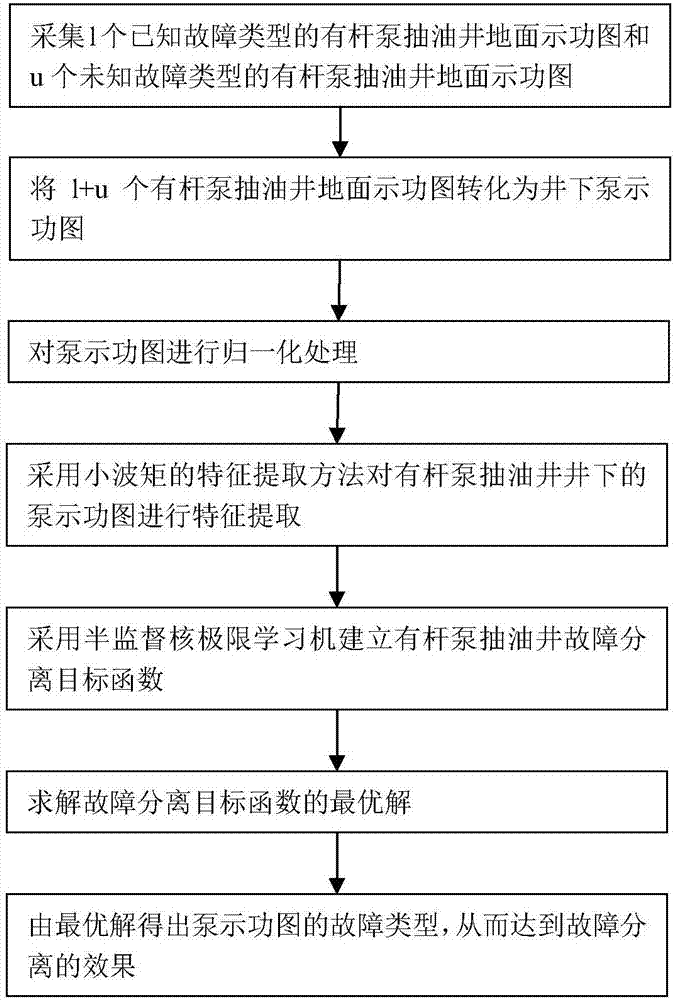
[0056] A rod pump fault isolation method, such as figure 1 shown, including the following steps:

[0057] Step 1: collect l surface dynamometer diagrams of rod pumped oil wells with known fault types and u ground dynamometer diagrams of rod pumped oil wells with unknown fault types;

[0058] In this embodiment, 100 surface dynamometer diagrams of rod pumped wells with known fault types and 180 surface dynamometer diagrams of rod pumped wells with unknown fault types to be separated are selected, among which the surface dynamometer diagrams of known fault types are There are 9 types of dynamometer diagrams, and “normal” is also regarded as a fault type here, which are: 12 “normal” type dynamometer diagrams on the surface of rod pump wells, 11 “insufficient fluid supply” type Surface dynamometer diagrams of rod pumped wells, 11 surface dynamometer diagrams of rod pumped ...


PUM


Abstract

The invention relates to a malfunction separating method for a sucker-rod pump pumping well. A small quantity of collected malfunction marked sucker-rod pump pumping well ground indicating diagrams and a large quantity of collected unmarked sucker-rod pump pumping well ground indicating diagrams are obtained and converted into down-hole pump indicating diagrams; through a wavelet invariant moment characteristic extracting method, the characteristic vector of a pump indicating diagram after normalization processing is extracted; and through a semi-supervised core limitation learning machine algorithm, the characteristic vector of the pump indicating diagram is trained and learned, so that malfunction separating of the sucker-rod pump pumping well is completed. According to the malfunction separating method for the sucker-rod pump pumping well, the characteristic vector of the pump indicating diagram extracted through the low frequency stage wavelet invariant moment can vividly describe the edge characteristics of the pump indicating diagram; through the semi-supervised core limitation learning machine algorithm with an added manifold regularization term, the sucker-rod pump pumping well is subjected to malfunction diagnosis, a lot of actual collected unmarked data of the sucker-rod pump pumping well are sufficiently utilized for training, and diagnosis accuracy is improved.

Description

technical field [0001] The invention belongs to the field of fault diagnosis of pumping wells, in particular to a method for fault separation of pumping wells with rod pumps. Background technique [0002] In the actual oil production process of the rod pump unit, the pump dynamometer diagram contains a lot of information about the working conditions of the pumping well. Therefore, analyzing the pump dynamometer diagram has become one of the most reliable means to determine the working conditions of the oil well. The general fault diagnosis method in the traditional oil recovery process relies on experts and on-site technical staff to analyze the pump dynamometer diagram. This method diagnoses cycle time If it is too long, the diagnosis of complex functional diagrams often cannot meet the needs of production. [0003] On the basis of the development of modern science and technology, many computer analysis methods based on pump dynamometer diagrams have attracted more and mor...

Claims


Application Information

Patent Timeline
IPC IPC(8): E21B47/009G06K9/46G06K9/62
CPCE21B47/009G06V10/40G06F18/24G06F18/214
Inventor 高宪文王明顺魏晶亮张平郑博元张遨张佳奇刘俊辰
Owner NORTHEASTERN UNIV
Why Eureka
Try Eureka