Remote sensing image change detection method and system based on mask classification

A remote sensing image and change detection technology, applied in instruments, computing, character and pattern recognition, etc., can solve problems such as high precision, dependence on initial cluster centers, and difficulty in automatically determining the number of categories

Inactive Publication Date: 2015-08-12
WUHAN UNIV
View PDF3 Cites 19 Cited by
  • Summary
  • Abstract
  • Description
  • Claims
  • Application Information

AI Technical Summary

Problems solved by technology

[0003] At present, the commonly used remote sensing image change detection methods include direct comparison method and post-classification comparison method. The former is simple and fast, but it can only quantitatively describe whether the target area has changed, and it is difficult to determine the nature of the change; the latter can provide information about the type of change , but it is necessary to carry out image classification twice and formulate a unified classification standard, and the detection accuracy is affected by the error propagation of separate classification
In addition, there is a phenomenon of mixed pixels in medium and high-resolution remote sensing images, and traditional "hard" classification methods cannot obtain high accuracy. Fuzzy C-means clustering (FCM) is a soft clustering algorithm that uses membership degrees to make classes There is no clear boundary between the cluster and the class, and it is effective to deal with mixed pixels, but there are defects such as over-reliance on the initial cluster center, difficulty in automatically determining the number of categories, and sensitivity to isolated point noise data.

Method used


Image

  • Remote sensing image change detection method and system based on mask classification
  • Remote sensing image change detection method and system based on mask classification
  • Remote sensing image change detection method and system based on mask classification

Examples


Embodiment Construction

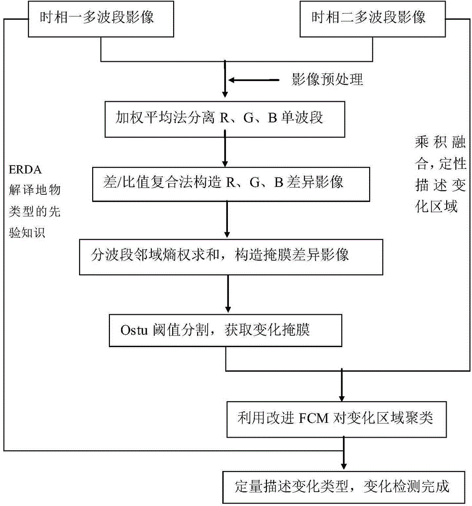
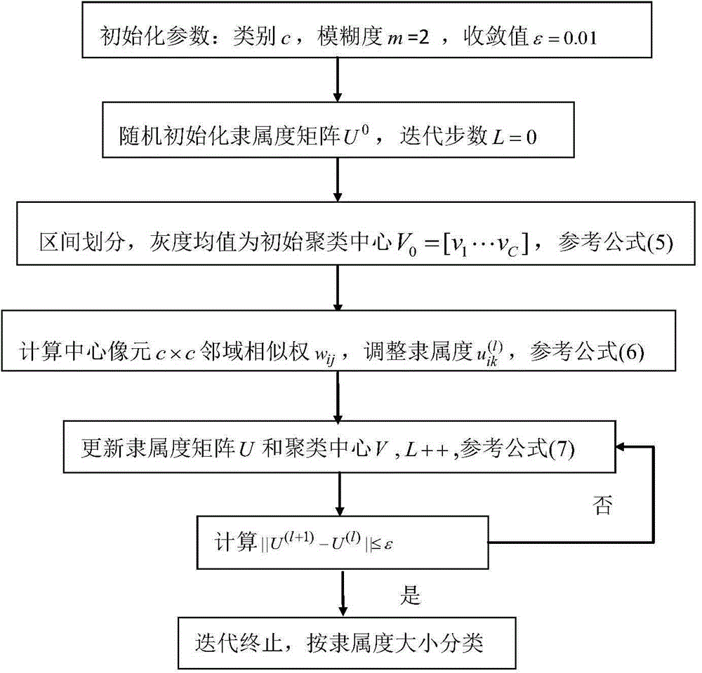
[0066] The present invention mainly designs two parts, namely: (1) the structure of the single-band difference image and the binary change mask and (2) the mask classification change detection. The technical solution of the present invention mainly includes the difference / ratio composite method to construct a single sub-band difference image, the Ostu threshold segmentation structure change mask, and the image change detection based on the fuzzy C-means clustering method and mask classification. The invention can qualitatively describe the change area and quantitatively describe the change type, and at the same time alleviate the influence of the single-band sensitivity difference caused by the same object with different spectrum and different object with the same spectrum on the false detection and missed detection of change detection, and can effectively suppress isolated noise interference, Avoiding local optima, etc., it also has better timeliness and accuracy.

[0067] Th...


PUM


Abstract

The invention provides a remote sensing image change detection method and system based on mask classification, and the method comprises the steps: 1, the preprocessing of a multiband remote sensing image; 2, the single-band separation of the multiband remote sensing image after preprocessing; 3, the constructing of a single-band difference image of two-phase single-band remote sensing images; 4, the construction of a change mask difference image, and cutting the change mask difference image based on an Otsu method; 5, the multiplication fusion of a change mask with one of the two-phase single-band remote sensing images, thereby obtaining a change region; 6, the clustering of the change region through a fuzzy C mean value method; and 7, determining the change type of the change region through combination of the prior knowledge of the ground object type of the other one of the two-phase single-band remote sensing images according to the clustering results of the change region. The method and system are resistant to nose interference, can alleviate local optimum effectively, can consider the qualitative and quantitative description of an image change process, and is high in change detection precision and reliability.

Description

technical field [0001] The invention belongs to the technical field of photogrammetry and remote sensing image application, in particular to a remote sensing image change detection method and system based on mask classification, which is suitable for real-time, automatic (or semi-automatic) detection of remote sensing image changes. Background technique [0002] Remote sensing image change detection is to detect the time-changing information of the ground objects in the area by analyzing the remote sensing images of the same area in different phases. With the rapid development of aerospace technology, remote sensing observation data has been more and more widely used due to its characteristics of real-time, fast, wide coverage, and high temporal and spatial resolution. How to effectively extract the change information in massive data and use it for the prevention of various natural disasters faced by the environment, agriculture, ecosystems and human beings has become a hot ...

Claims


Application Information

Patent Timeline
IPC IPC(8): G06K9/62G06K9/54
CPCG06V10/20G06F18/23211G06F18/23
Inventor 万幼川姜莹李刚
Owner WUHAN UNIV
Why Eureka
Try Eureka