Valve piston, and slide valve having a valve piston

A valve piston, slide valve technology, applied in the field of valve piston

Active Publication Date: 2017-07-07
ROBERT BOSCH GMBH
View PDF13 Cites 0 Cited by
  • Summary
  • Abstract
  • Description
  • Claims
  • Application Information

AI Technical Summary

Problems solved by technology

[0004] The disadvantage of the valve piston is that when the piston moves into the closed position of the valve, the surrounding edge of the piston has to be moved under or i

Method used


Image

  • Valve piston, and slide valve having a valve piston
  • Valve piston, and slide valve having a valve piston
  • Valve piston, and slide valve having a valve piston

Examples


Embodiment Construction

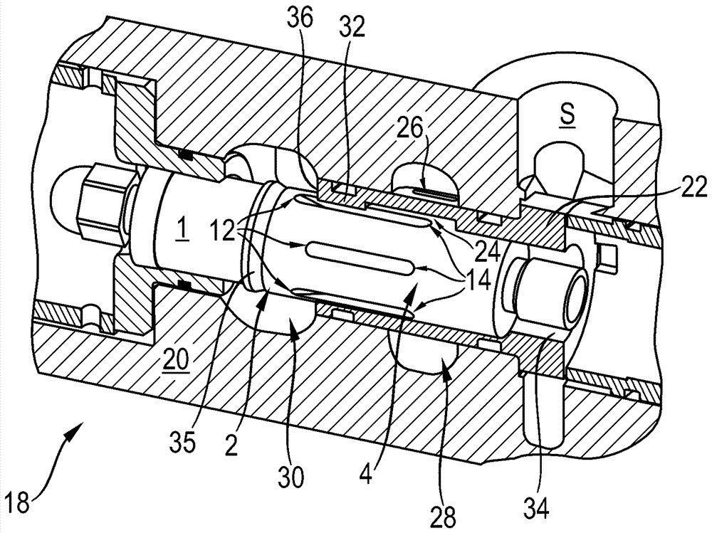
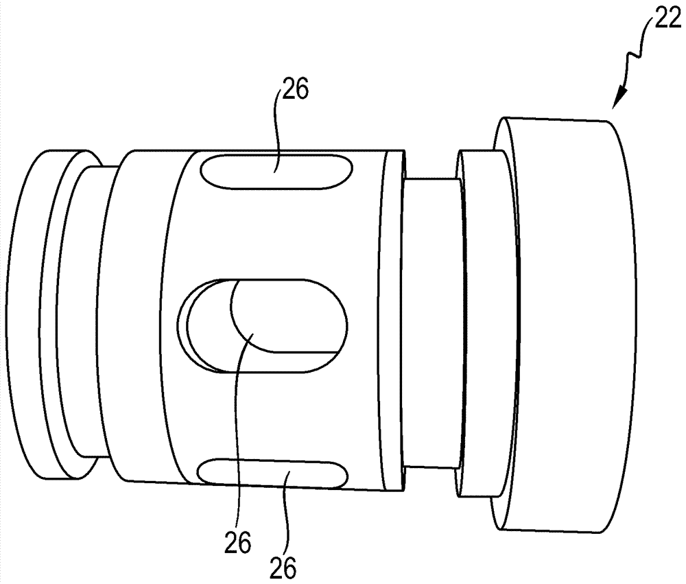
[0031] figure 1 Shown is a view of an embodiment of a valve piston 1 according to the invention. It has a cylindrical section with two axially spaced regions 2 , 4 , which are cylindrically designed over the entire surface and in this case have the same diameter. Between these two areas 2, 4, five longitudinal grooves 6 are evenly arranged on the circumference of the valve piston 1, and these longitudinal grooves are used to connect two ( figure 1 not shown in the pressure chamber.

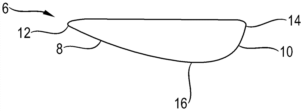
[0032] figure 2 The longitudinal groove 6 is shown in a cross-sectional view of the valve piston 1 . It can be seen here that its depth increases relatively slowly from the first region 2 , whereas its depth increases relatively rapidly from the second region 4 . This results in a relatively flat first edge 8 and a relatively steep second edge 10 . Starting from the first end section 12 , the first edge 8 initially descends approximately constantly, while the second edge 10 has a decreasing ...


PUM


Abstract

A valve piston includes a section that has a circular-cylindrical configuration with a constant diameter. A plurality of longitudinal grooves are made in the section with the grooves parallel to one another and distributed uniformly on the circumference. The remaining webs enable the section of the valve piston to be moved in the valve without tilting. Each longitudinal groove has one steeper flank and one less steep flank. The steeper flank is set against a pressure medium that flows in.

Description

technical field [0001] The invention relates to a valve piston according to the preamble of claim 1 and to a slide valve having such a valve piston. Background technique [0002] Valve pistons for slide valves are known from the prior art which have a radial step which is formed by a piston sleeve and a piston section which is radially tapered relative to the piston sleeve. A peripheral piston-side control edge is formed on this step. In the installed state of the valve piston in the valve housing and during operation of the valve formed in this way, the piston-side control edge moves relative to the surrounding control edge of the valve housing. As a result, the circumferential ring opening is opened and adjusted in size, or the ring opening shrinks and finally closes when the valve piston moves in the opposite direction. [0003] In documents US 2,747,612 and US 4,923,172 valves are disclosed whose valve pistons do not have radial steps. Alternatively, a circumferential...

Claims


Application Information

Patent Timeline
IPC IPC(8): F16K11/07F16K27/04
CPCF16K11/07F16K27/041F16K15/021F16K15/18F16K17/26F16K17/34F16K31/1223F16K47/04
Inventor D.格拉赫K.哈布尔
Owner ROBERT BOSCH GMBH
Why Eureka
Try Eureka