Pipeline connector device

A technology for connecting heads and pipelines, which is applied in the field of pipeline connecting devices, and can solve problems such as large safety risks

Inactive Publication Date: 2017-07-07
PETROCHINA CO LTD
View PDF8 Cites 5 Cited by
  • Summary
  • Abstract
  • Description
  • Claims
  • Application Information

AI Technical Summary

Problems solved by technology

[0005] The main purpose of the present invention is to provide a pipeline coupling device to solve the problem in the prior art that there is a relatively large safety risk in connecting pipelines by means of fire couplings

Method used


Image

  • Pipeline connector device
  • Pipeline connector device
  • Pipeline connector device

Examples


Embodiment Construction

[0033] It should be noted that, in the case of no conflict, the embodiments in the present application and the features in the embodiments can be combined with each other. The present invention will be described in detail below with reference to the accompanying drawings and examples.

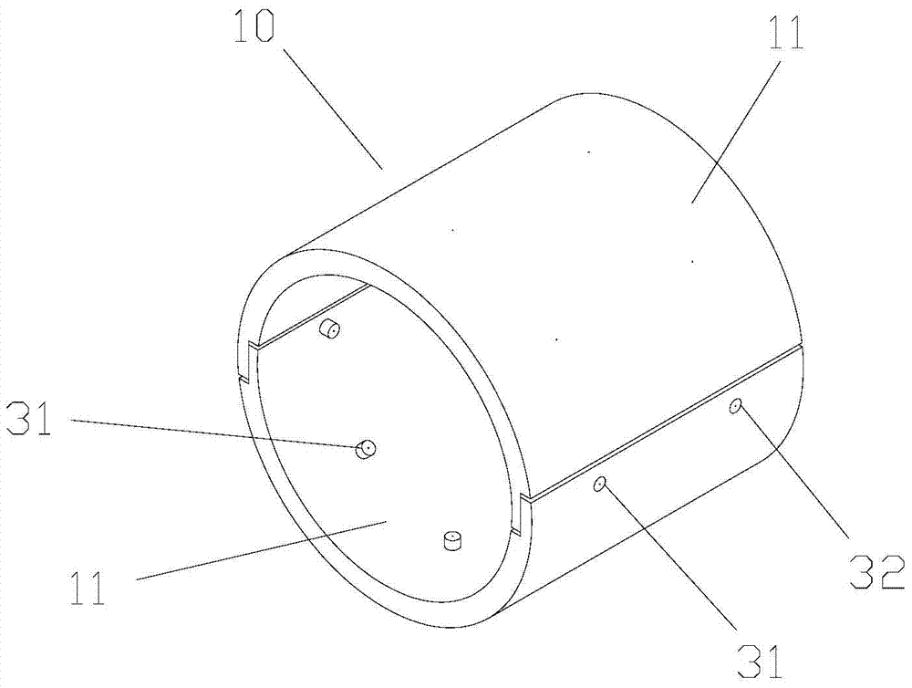
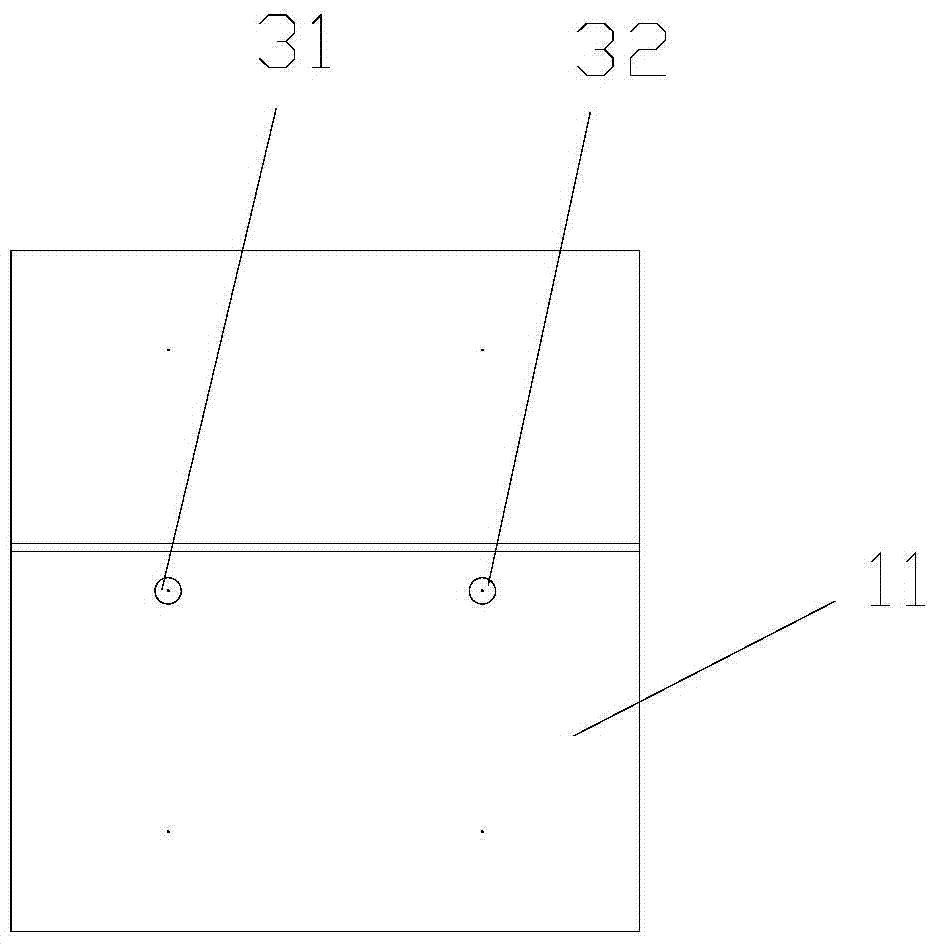
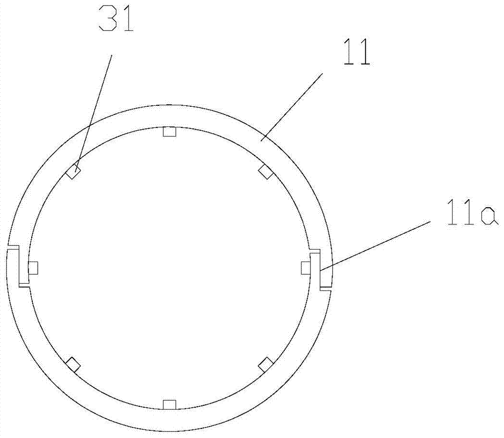
[0034] This embodiment provides a pipeline connector device, please refer to Figure 1 to Figure 9 , the pipeline joint device includes: a fixed slip 10, the fixed slip 10 is composed of a plurality of tiles 11 spliced ​​sequentially along its circumference, and each tile 11 is wrapped in the first pipe body 21 and the second pipe to be connected. On the pipe body 22; wherein, at least one tile plate 11 is provided with a first positioning member 31 for being inserted into the first positioning hole 211 of the first pipe body 21 for positioning, and at least one tile plate 11 is provided with a first positioning member 31 for inserting The second positioning member 32 is disposed in the second...


PUM


Abstract

The invention provides a pipeline connector device. The pipeline connector device comprises a pair of fixing slips. The pair of fixing slips is composed of multiple slips plates which are sequentially spliced in the circumferential direction of the fixing slips. Each slips plate is wrapped around a first pipe body and a second pipe body to be connected. At least one slips plate is provided with a first locating piece used for being inserted into a first locating hole of the first pipe body for locating. At least one slips plate is provided with a second locating piece used for being inserted into a second locating hole of the second pipe body for locating. The pipeline connector device solves the problem that in the prior art, large safety risk exists when a hot work joint manner is adopted.

Description

technical field [0001] The invention relates to the field of oil exploitation, in particular to a pipeline connector device. Background technique [0002] At present, in the daily production and operation of oilfields, oil and gas metal pipelines are prone to corrosion and scaling and pipeline leakage due to long-term operation and the influence of high-temperature, high-pressure, and highly corrosive fluid media, which will affect the safe operation of pipelines. [0003] When repairing and replacing damaged pipelines, conventional maintenance methods often require hot-fire joints, especially in gathering stations and oil-gas-intensive places, where there is a risk of fire and explosion when performing hot-fire operations. [0004] In addition, in order to meet the fire safety conditions, it is necessary to invest a lot of manpower and material resources in pre-construction preparations, and with the increase of the fire level, the requirements are becoming more and more st...

Claims


Application Information

Patent Timeline
Patent Type & Authority Applications(China)
IPC IPC(8): F16L21/06F16L13/11
CPCF16L21/06F16L13/11
Inventor 梁爱国
Owner PETROCHINA CO LTD
Why Eureka
Try Eureka