A current measuring coil and a manufacturing method of the current measuring coil

A technology of current measuring coils and conductive coils, which is applied in the direction of measuring electrical variables, measuring devices, and manufacturing measuring instruments, etc., can solve the problems of increasing the measurement error of current measuring coils, inconsistent cross-sectional areas, and uneven distribution of windings, etc., to improve The effect of measurement accuracy, uniform distribution, and reduced manpower input

Active Publication Date: 2019-05-28
ZHENGZHOU WEIDA ELECTRONICS CO LTD +1
View PDF6 Cites 0 Cited by
  • Summary
  • Abstract
  • Description
  • Claims
  • Application Information

AI Technical Summary

Problems solved by technology

[0003] The windings of the existing current measuring coils are made by winding wires on the surface of the skeleton. Due to the manual winding of the wires, the uneven distribution of the windings and the inconsistent cross-sectional area lead to large differences in the measurement results. At the same time, because the winding and the skeleton are greatly affected by thermal expansion, it will produce difficult-to-estimate deformation during measurement, which will further increase the measurement error of the current measurement coil

Method used


Image

  • A current measuring coil and a manufacturing method of the current measuring coil
  • A current measuring coil and a manufacturing method of the current measuring coil
  • A current measuring coil and a manufacturing method of the current measuring coil

Examples


Embodiment Construction

[0026] The following will clearly and completely describe the technical solutions in the embodiments of the present invention with reference to the accompanying drawings in the embodiments of the present invention. Obviously, the described embodiments are only some, not all, embodiments of the present invention. Based on the embodiments of the present invention, all other embodiments obtained by persons of ordinary skill in the art without making creative efforts belong to the protection scope of the present invention.

[0027] In order to make the above objects, features and advantages of the present invention more comprehensible, the present invention will be further described in detail below in conjunction with the accompanying drawings and specific embodiments.

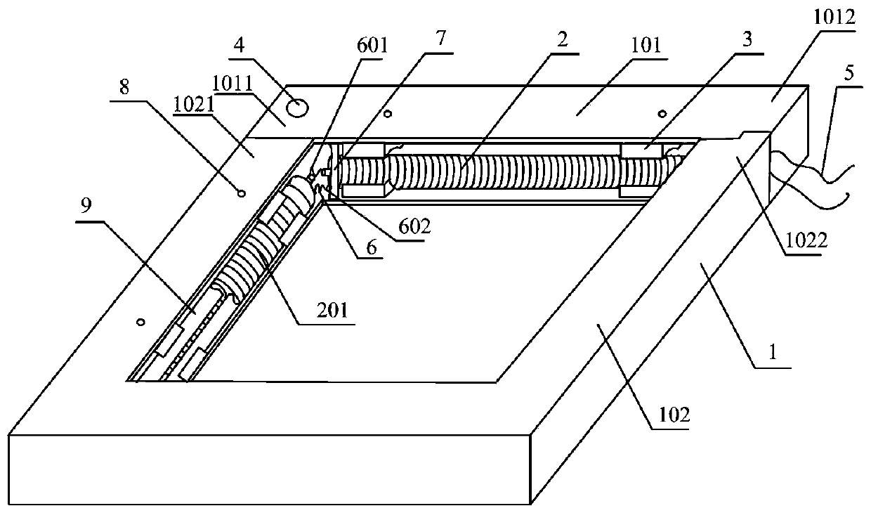
[0028] figure 1 It is a structure diagram of the current measuring coil of Embodiment 1 of the current measuring coil of the present invention.

[0029] see figure 1 , the current measurement coil, including: a ...


PUM


Abstract

The present invention discloses a current measuring coil, and a manufacturing method of the current measuring coil. The current measuring coil comprises a magnetic shielding frame, a framework coil and an insulated support block. The magnetic shielding frame is of a closed frame structure. The inner side of the magnetic shielding frame is provided with a groove. The insulated support block is embedded between the inner wall of the groove and the outer wall of the framework coil. The framework coil embedded in the insulated support block. The framework coil is formed through the series connection of a plurality of columnar windings. Each columnar winding comprises a framework, a center conductor and a conductive coil. The framework, made of non-ferromagnetic materials, is prepared through the injection molding process to be of a columnar structure. The center conductor is formed at the center of the framework through the injection molding process. The center conductor extends out of the two ends of the framework. The outer surface of the framework, between the two ends of the framework, is provided with a spiral groove. The conductive coil is plated inside the spiral groove. According to the technical scheme of the current measuring coil, and the manufacturing method of the current measuring coil, the consistency of the cross-sectional areas of windings can be ensured and the windings are uniformly distributed. The measurement accuracy is effective improved.

Description

technical field [0001] The invention relates to the technical field of current measurement, in particular to a current measurement coil and a manufacturing method of the current measurement coil. Background technique [0002] The current measuring coil, also known as the Rogowski coil (Rogowski coil), is a toroidal coil that is uniformly and densely wound on a non-magnetic skeleton with a uniform cross-sectional area. It is equivalent to a sensor that can be directly placed on the current-carrying conductor to measure the alternating current. When measuring, the current-carrying conductor to be measured is placed on the central axis of the current measuring coil. When the alternating current passes through the central axis of the current measuring coil along the conductor, a correspondingly changing magnetic field is generated in the current measuring coil, so that the current measuring coil induces Electric potential, by measuring the induced electromotive force output by ...

Claims


Application Information

Patent Timeline
Patent Type & Authority Patents(China)
IPC IPC(8): G01R3/00G01R15/20
CPCG01R3/00G01R15/202
Inventor 王程远田闽哲崔陆军徐二强赵玉富张龙段鑫田耕梁德亮
Owner ZHENGZHOU WEIDA ELECTRONICS CO LTD
Why Eureka
Try Eureka