
Automobile data recorder with sunscreen function
A driving recorder and function technology, which is applied in the registration/indication of vehicle operation, instruments, registration/indication, etc., can solve the problems of damage to the photosensitive element and reduce the service life of the driving recorder, so as to improve the service life, improve the service life, The effect of improving safety
- Summary
- Abstract
- Description
- Claims
- Application Information
AI Technical Summary
Problems solved by technology
Method used
Image

Examples
Embodiment 1
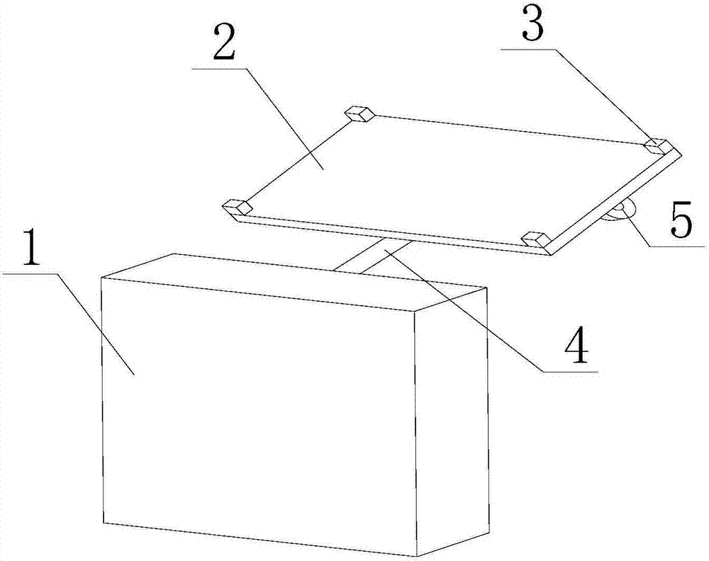
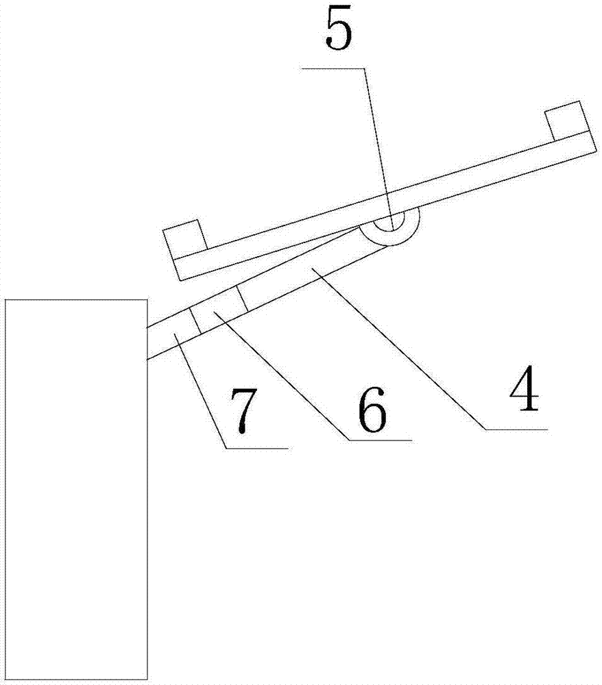
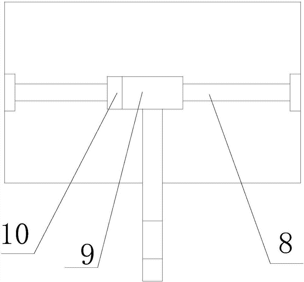
[0027] like figure 1 , figure 2 and image 3 As shown, the driving recorder with sun protection function of the present invention includes an imaging device 1, a reflector 2, a rotating rod 4, a crossbar joint 5, a crossbar 8 and a sleeve 9; the crossbar joint 5 is arranged on the reflector 2 bottom surface, and the cross bar 8 is fixedly installed on the bottom surface of the reflective plate 2 through the cross bar joint 5; The other end is connected to the camera device 1; the axis of the cross bar 8 is perpendicular to the axis of the rotating pick rod 4; the cross bar 8 rotates in the sleeve 9 around the axis of the cross bar 8; Rod 4 axis rotation.
[0028] During the implementation of this embodiment, the crossbar joint 5 is arranged on the bottom surface of the reflector 2, and the crossbar 8 is fixedly installed on the bottom surface of the reflector 2 through the crossbar joint 5; The tube 9 is connected to the cross bar 8, and the other end of the rotating rod ...
Embodiment 2
[0030] like figure 1 , figure 2 and image 3 As shown, on the basis of Embodiment 1, this embodiment also includes a pole motor 6 and a crossbar motor 10; the pole motor 6 is arranged on the rotating pole 4, and drives the rotating pole 4 to rotate 4 axis rotation; the crossbar motor 10 is arranged on the crossbar 8, and drives the crossbar 8 to rotate around the axis of the crossbar 8.
[0031] During the implementation of this embodiment, the pole motor 6 drives the rotating pole 4 to rotate around the axis of the rotating pole 4, and the crossbar motor 10 drives the crossbar 8 to rotate around the axis of the crossbar 8, which realizes the motorization of the movement of the reflector 2 and improves the Reflectors adjust efficiency.
Embodiment 3
[0033] like figure 1 , figure 2 , image 3 and Figure 4 As shown, on the basis of Embodiment 2, this embodiment further includes a control device 7 ; the control device 7 is arranged on the rotating pole 4 and controls the movement of the pole motor 6 and the crossbar motor 10 . It also includes four photosensitive sensors 3; the four photosensitive sensors 3 are arranged on the top surface of the reflective plate 2; the four photosensitive sensors 3 form four vertices of a quadrilateral, and each interior angle of the quadrilateral is less than 180° . The control device 7 includes: a control module for controlling the movement of the pole motor 6 and the crossbar motor 10 according to the light intensity detected by the four photosensitive sensors 3 .
[0034] During the implementation of this embodiment, the control module is preferably a Cortex-A7 chip, and the photosensitive sensor is preferably LXD125. The control module controls the movement of the pole motor 6 and...
PUM
 Abstract
Description
Claims
Application Information