
Distributed power generation-based power coordinated control method of intelligent microgrid system

A distributed power generation and coordinated control technology, applied in photovoltaic power generation, wind power generation, electrical components, etc., can solve the problems of mismatching output power and external load, large output power fluctuation, and sudden change of wind and solar power generation current.

Inactive Publication Date: 2017-07-07
NORTH CHINA ELECTRIC POWER UNIV (BAODING)
View PDF3 Cites 11 Cited by
  • Summary
  • Abstract
  • Description
  • Claims
  • Application Information

AI Technical Summary

Problems solved by technology

At the same time, the wind power generation sub-system and the photovoltaic power generation sub-system are two geographically separated subsystems, but most of the control methods of conventional wind-solar hybrid power generation systems are based on centralized control, which obviously makes the wind-solar hybrid system still have deficiencies; while independent The power generation of new energy such as wind energy or solar energy will lead to large fluctuations in output power, and there are problems such as obvious peak and valley phenomena, mismatch between output power and external loads, sudden changes in the current of wind and solar hybrid power generation, and frequent charging and discharging of batteries.

Method used


Image

  • Distributed power generation-based power coordinated control method of intelligent microgrid system
  • Distributed power generation-based power coordinated control method of intelligent microgrid system
  • Distributed power generation-based power coordinated control method of intelligent microgrid system

Examples


Embodiment Construction

[0067] In order to make the objectives, technical solutions and advantages of the present invention clearer, the technical solutions in the embodiments of the present invention will be described in more detail below in conjunction with the drawings in the embodiments of the present invention. In the drawings, the same or similar reference numerals denote the same or similar elements or elements having the same or similar functions throughout. The described embodiments are some, but not all, embodiments of the invention. The embodiments described below by referring to the figures are exemplary and are intended to explain the present invention and should not be construed as limiting the present invention. Based on the embodiments of the present invention, all other embodiments obtained by persons of ordinary skill in the art without creative efforts fall within the protection scope of the present invention. Embodiments of the present invention will be described in detail below ...


PUM


Abstract

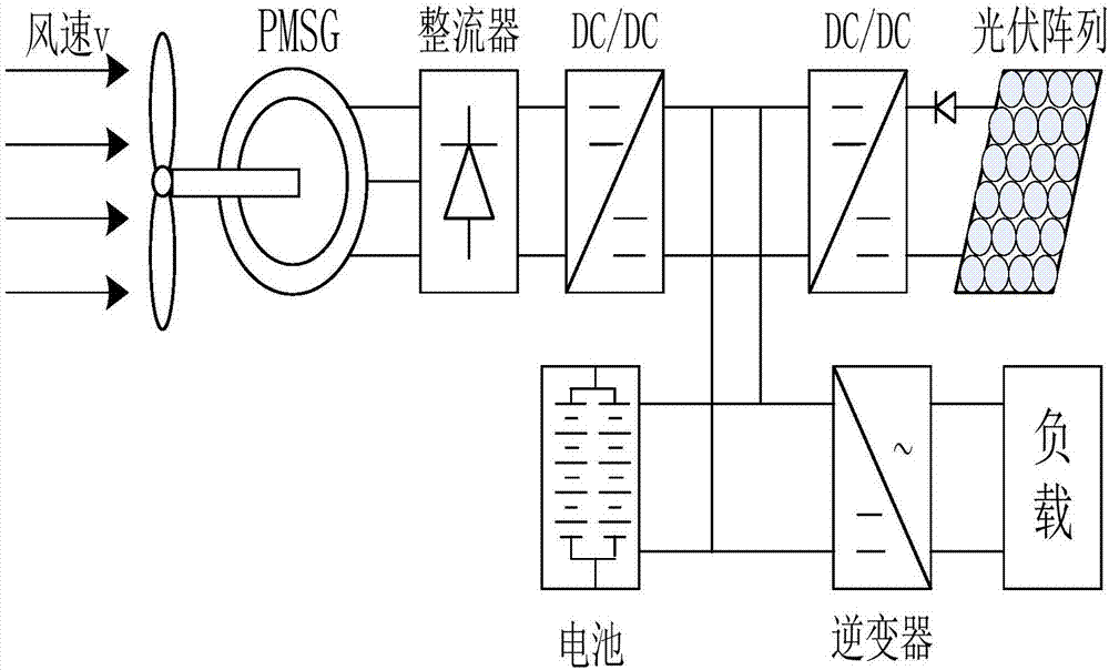
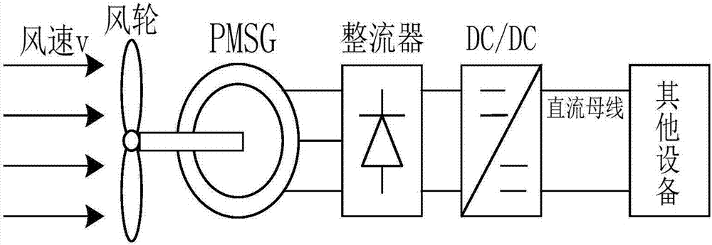
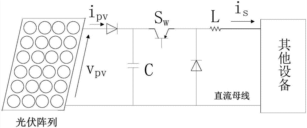
The invention discloses a distributed power generation-based power coordinated control method of an intelligent microgrid system. The power coordinated control method of the intelligent microgrid system comprises the following steps of 1, respectively building mathematical models of a wind power generation sub-system, a photovoltaic power generation sub-system and a storage battery energy storage sub-system according to a working principle of an intelligent microgrid; 2, designing an upper-layer distributed model forecast controller, wherein the wind power generation sub-system, the photovoltaic power generation sub-system and the storage battery energy storage sub-system are used for effectively and reasonably coordinating an output power by the upper-layer distributed model forecast controller, and the output power is transferred to a lower-layer sliding-mode variable structure sub-controller; 3, designing a first sliding-mode variable structure controller and a second sliding-mode variable structure controller; 4, designing a third sliding-mode variable structure controller and a fourth sliding-mode variable structure controller; and 5, switching control modes of the first sliding-mode variable structure controller, the second sliding-mode variable structure controller, the third sliding-mode variable structure controller and the fourth sliding-mode variable structure controller and controlling a storage battery switch.

Description

technical field [0001] The invention relates to the technical field of smart microgrid control and application, in particular to a distributed power generation-based smart microgrid system power coordination control method. Background technique [0002] With the progress of society and the rapid development of science and technology, electricity, as the most convenient and clean energy, has become the main way for people to use energy. However, while the global power consumption continues to increase, it has also caused a series of problems such as the depletion of fossil energy and the deterioration of the environment and ecology. In recent years, the world energy crisis and successive large-scale power outages have exposed the shortcomings of traditional energy supply models and power networks, and power technology and construction models are in urgent need of improvement. Therefore, vigorously developing and utilizing new energy has become a strategic choice for countrie...

Claims


Application Information

Patent Timeline
Patent Type & Authority Applications(China)
IPC IPC(8): H02J3/46H02J3/38H02J3/32
CPCH02J3/32H02J3/385H02J3/386H02J3/46Y02B10/10Y02E10/56Y02E10/76Y02E70/30
Inventor 马苗苗邵黎阳刘向杰
Owner NORTH CHINA ELECTRIC POWER UNIV (BAODING)
Learn More