

Automobile part forging die assembly
A technology of auto parts and molds, applied in the direction of manufacturing tools, forging/pressing/hammer devices, forging/pressing/hammering machinery, etc., can solve the problems of easy misalignment, easy backflow, difficult to take out, etc., to prevent misalignment, The effect of preventing material flow from being blocked and preventing lamination cracks
- Summary
- Abstract
- Description
- Claims
- Application Information
AI Technical Summary
Problems solved by technology
Method used
Image

Examples
Embodiment 1
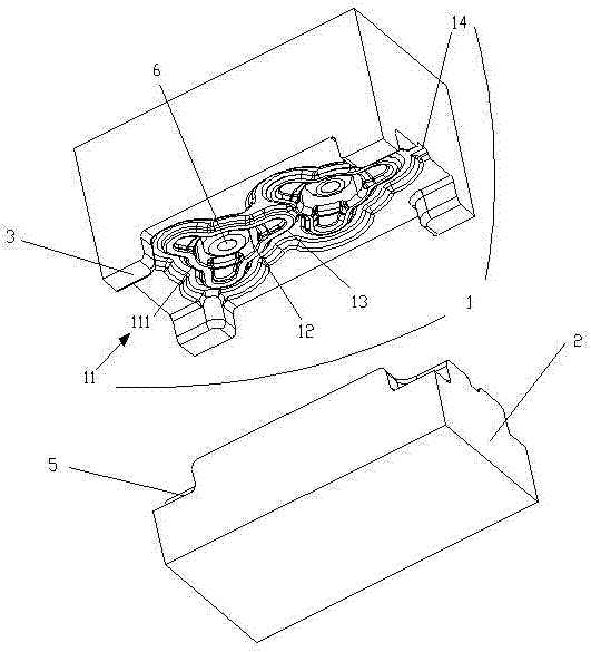
[0026] Such as Figure 1-2 As shown, this embodiment discloses a forging die assembly for auto parts, including an upper die 1 and a lower die 2 that cooperate with each other. Both the bottom of the upper mold 1 and the top of the lower mold 2 are provided with mold cavities. The cavity shapes of the upper mold 1 and the lower mold 2 of the present invention are corresponding.
[0027] The mold cavity of the upper mold 1 includes an upper resistance bridge 11 , an upper product cavity 12 , and an upper flash groove 13 . The upper resistance bridge 11 has a ring structure, an upper product cavity 12 is formed on the inner side, and an upper flash groove 13 is surrounded on the outer side. One or several discontinuous sections of the upper resistance bridge 11 are arched outwards to form an upper fillet structure 111 .
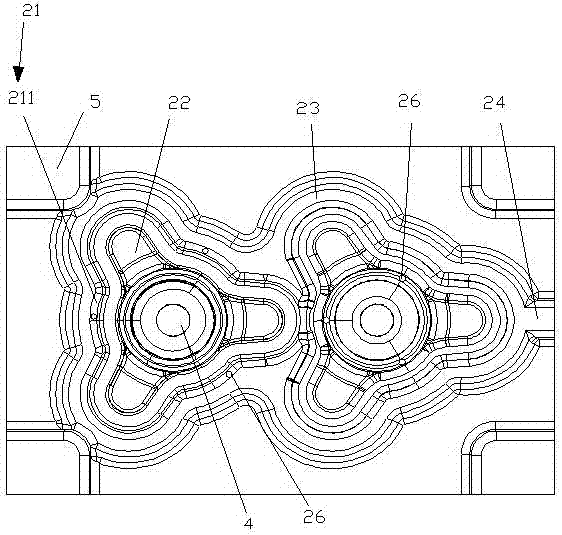
[0028] The mold cavity of the lower mold 2 includes a lower resistance bridge 21 , a lower product cavity 22 , and a lower flash groove 23 . The lower resi...
Embodiment 2
[0035] Such as Figure 1-2 As shown, this embodiment discloses a forging die assembly for auto parts, including an upper die 1 and a lower die 2 that cooperate with each other. Both the bottom of the upper mold 1 and the top of the lower mold 2 are provided with mold cavities. The cavity shapes of the upper mold 1 and the lower mold 2 of the present invention are corresponding.
[0036] The mold cavity of the upper mold 1 includes an upper resistance bridge 11 , an upper product cavity 12 , an upper flash groove 13 , and an upper jaw 14 . The upper resistance bridge 11 has a ring structure, an upper product cavity 12 is formed on the inner side, and an upper flash groove 13 is surrounded on the outer side. One or several discontinuous sections of the upper resistance bridge 11 are arched outwards to form an upper fillet structure 111 . An upper jaw 14 is provided on the upper flash groove 13 , and the upper jaw 14 is connected to the edge of the upper mold 1 .
[0037] The...
Embodiment 3
[0041] Such as Figure 1-2 As shown, this embodiment discloses a forging die assembly for auto parts, including an upper die 1 and a lower die 2 that cooperate with each other. Both the bottom of the upper mold 1 and the top of the lower mold 2 are provided with mold cavities. The cavity shapes of the upper mold 1 and the lower mold 2 of the present invention are corresponding.
[0042] The mold cavity of the upper mold 1 includes an upper resistance bridge 11 , an upper product cavity 12 , an upper flash groove 13 , and an upper jaw 14 . The upper resistance bridge 11 has a ring structure, an upper product cavity 12 is formed on the inner side, and an upper flash groove 13 is surrounded on the outer side. One or several discontinuous sections of the upper resistance bridge 11 are arched outwards to form an upper fillet structure 111 . An upper jaw 14 is provided on the upper flash groove 13 , and the upper jaw 14 is connected to the edge of the upper mold 1 .
[0043] The m...
PUM
 Abstract
Description
Claims
Application Information