
Locking device of edge grinding machine and edge grinding machine

A technology of locking device and edging machine, which is applied in the direction of machine tools suitable for grinding workpiece edges, grinding racks, and parts of grinding machine tools, and can solve problems such as high maintenance costs, looseness, and poor fixing effects , to achieve the effect of improving maintenance costs and preventing wear problems

Pending Publication Date: 2017-07-11
GUANGDONG EDING IND
View PDF5 Cites 0 Cited by
  • Summary
  • Abstract
  • Description
  • Claims
  • Application Information

AI Technical Summary

Problems solved by technology

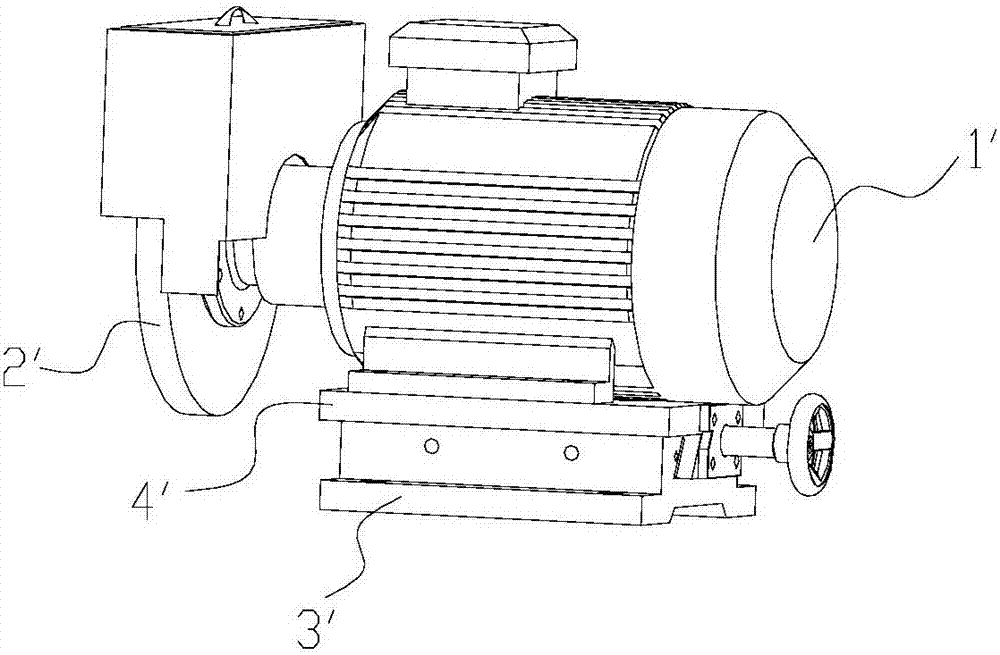
[0004] However, the problem with this locking method is: (1) the screw directly bears against the sliding seat of the grinding head, and only two points are fixed in contact. Since the edger will vibrate all the time during the working process, the screw and the sliding seat of the grinding head The point of contact will be easy to wear. After wear, the fixing effect will not be good, and the screw will be loosened. It is necessary to tighten the screw further, but the loose state cannot be found through general observation, and the depth of the screw cannot be screwed in. accurately grasped
(2) The sliding seat of the grinding head needs to be replaced after wear and tear, the cost is high before the operation is complicated, and the maintenance cost is high

Method used


Image

  • Locking device of edge grinding machine and edge grinding machine
  • Locking device of edge grinding machine and edge grinding machine
  • Locking device of edge grinding machine and edge grinding machine

Examples


Embodiment Construction

[0022] Below, in conjunction with accompanying drawing and specific embodiment, the present invention is described further:

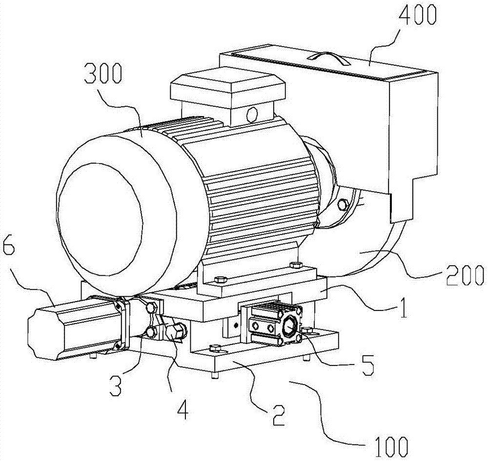
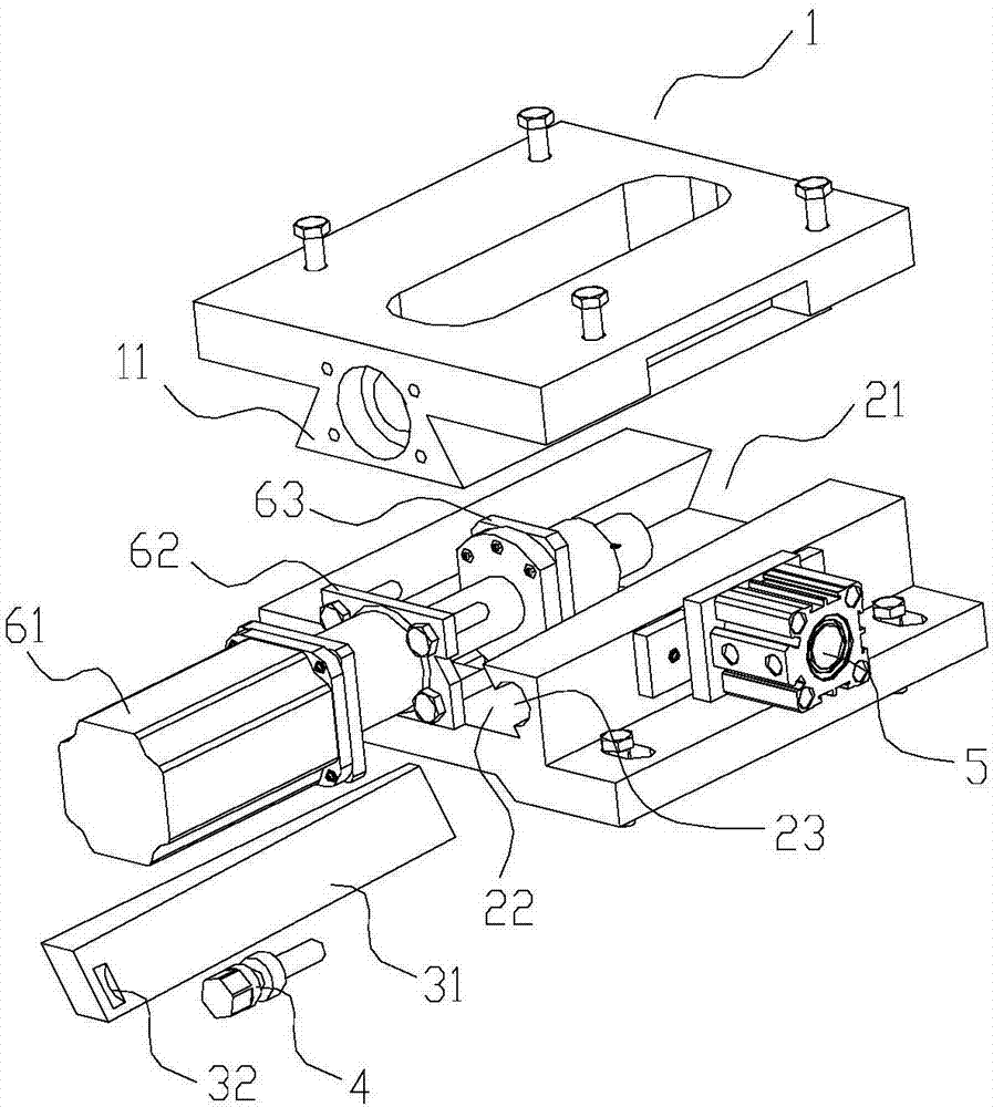
[0023] Such as Figure 2-4 As shown, a locking device 100 for an edger includes a grinding head sliding seat 1, a base 2, a locking plate 3 and an adjusting bolt 4; Convex is provided with the limit block 11 that cooperates and locks with limit groove; The limit block of described grinding head sliding seat can be slidably installed in the limit groove of base; The contact position of described base and grinding head slide seat is provided with There is a slot 22, the locking plate is inserted in the slot, and the locking plate is fastened in the slot by adjusting bolts.

[0024] The locking device of the edging machine of the present invention is inserted into the slot through the locking plate, and the adjusting bolt is tightened to the tightest state, so that the sliding seat of the grinding head and the base are pressed against each other, and the ...


PUM


Abstract

The invention discloses a locking device of an edge grinding machine and the edge grinding machine. The locking device of the edge grinding machine comprises a grinding head sliding seat, a base, a locking plate and an adjusting bolt. A limiting groove is formed in the base in a concave mode. A limiting block which is matched with and locked in the limiting groove is arranged on the grinding head sliding seat in a convex mode. The limiting block of the grinding head sliding seat can be slidably installed in the limiting groove of the base. Inserting grooves are formed in the parts, in contact with the grinding head sliding seat, of the base. The locking plate is inserted into the inserting grooves and fastened into the inserting grooves through the adjusting bolt. According to the locking device of the edge grinding machine, the locking plate is inserted into the inserting grooves, the adjusting bolt is screwed to the tightest state, the grinding head sliding seat and the base are made to get close to each other, the locking plate is in surface contact with the grinding head sliding seat and the base, thus, the grinding head sliding seat is fixedly connected with the base, and abrasion between the grinding head sliding seat and the base of the locking device can be effectively prevented.

Description

technical field [0001] The invention relates to the field of building material equipment, more specifically, to an edger locking device and an edger in the ceramic equipment industry. Background technique [0002] The edging machine chamfering produced by four-side grinding in the building material industry such as ceramic material, glass material, marble material and artificial stone material is mainly used for four-side grinding and shaping to ensure the shape and size requirements of ceramic tiles. [0003] The existing edging machine includes a main body of an edging head and a base, the main body of the edging head can move back and forth on the base, and a locking device is arranged between the two to realize the fixed connection between the main body of the edging head and the base. In the actual use of the edging machine, the edging head must advance to a position suitable for the width of the tile to polish it; in addition, the grinding wheel on the main body of the...

Claims


Application Information

Patent Timeline
IPC IPC(8): B24B9/06B24B41/00B24B41/02
CPCB24B9/06B24B41/00B24B41/02
Inventor 陈国平龙永华关光明冯竞浩
Owner GUANGDONG EDING IND
Learn More