
Chain cleaning device

A technology for cleaning devices and chains, applied to metal chains, cleaning methods and utensils, cleaning methods using tools, etc., can solve problems such as difficult cleaning, wear of inner chain plates 203 and outer chain plates 204, etc., to avoid wear problems, Ensure the effect of the cleanup effect

Pending Publication Date: 2022-03-18
河北华丰能源科技发展有限公司
View PDF0 Cites 0 Cited by
  • Summary
  • Abstract
  • Description
  • Claims
  • Application Information

AI Technical Summary

Problems solved by technology

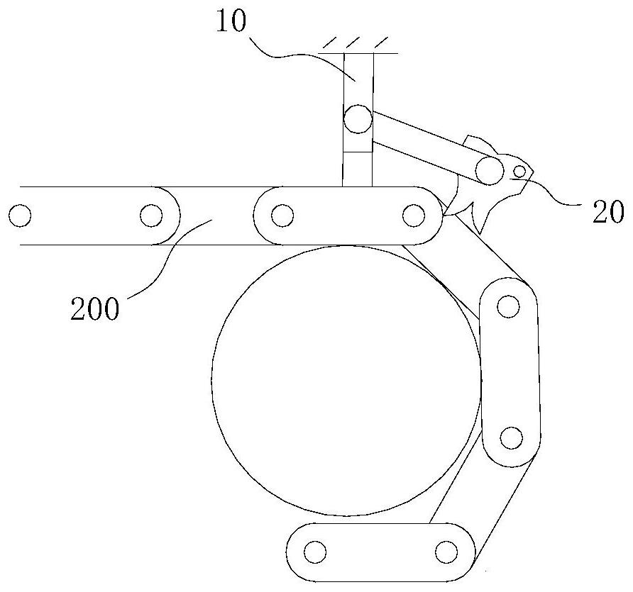
It can be understood that when the above-mentioned chain 200 is used to drive the beating roller to roll back and forth on the upper end surface of the final formed briquette, coal dust will be deposited on the upper end surfaces of the inner chain plate 203 and the outer chain plate 204 of the chain 200, but the chain 200 In the process of working, it is necessary to add lubricating oil at the place where the chain 200 matches the sprocket, so that the coal powder deposited on the upper end surfaces of the inner chain plate 203 and the outer chain plate 204 of the chain 200 will become viscous. It is not easy to fall off from the corresponding inner chain plate 203 and outer chain plate 204. As the chain 200 continues to move, this part of coal powder will enter the contact position between the inner chain plate 203 and the outer chain plate 204, thereby triggering the internal chain Wear between plate 203 and outer link plate 204
[0004] It can be understood that it is easy to scrape the viscous pulverized coal off the plane parts placed on the upper end faces of the inner chain plate 203 and the outer chain plate 204 by using a conventional cleaner, but it is located on the arc surface of the inner chain plate 203 and the outer chain plate 204. The viscous pulverized coal on the chain 200 is difficult to clean with a conventional sweeper. For this reason, a chain cleaning device is provided for cleaning the viscous pulverized coal on the inner chain plate 203 and the outer chain plate 204 of the chain 200. appears to be particularly necessary

Method used


Image

  • Chain cleaning device
  • Chain cleaning device
  • Chain cleaning device

Examples


Embodiment Construction

[0027] The following will clearly and completely describe the technical solutions in the embodiments of the present invention with reference to the accompanying drawings in the embodiments of the present invention. Obviously, the described embodiments are only some, not all, embodiments of the present invention. Based on the embodiments of the present invention, all other embodiments obtained by persons of ordinary skill in the art without making creative efforts belong to the protection scope of the present invention.

[0028] Unless otherwise defined, all technical and scientific terms used herein have the same meaning as commonly understood by one of ordinary skill in the technical field of the invention. The terms used herein in the description of the present invention are for the purpose of describing specific embodiments only, and are not intended to limit the present invention.

[0029] see figure 1 , the chain cleaning device claimed in the present invention is set at...


PUM


Abstract

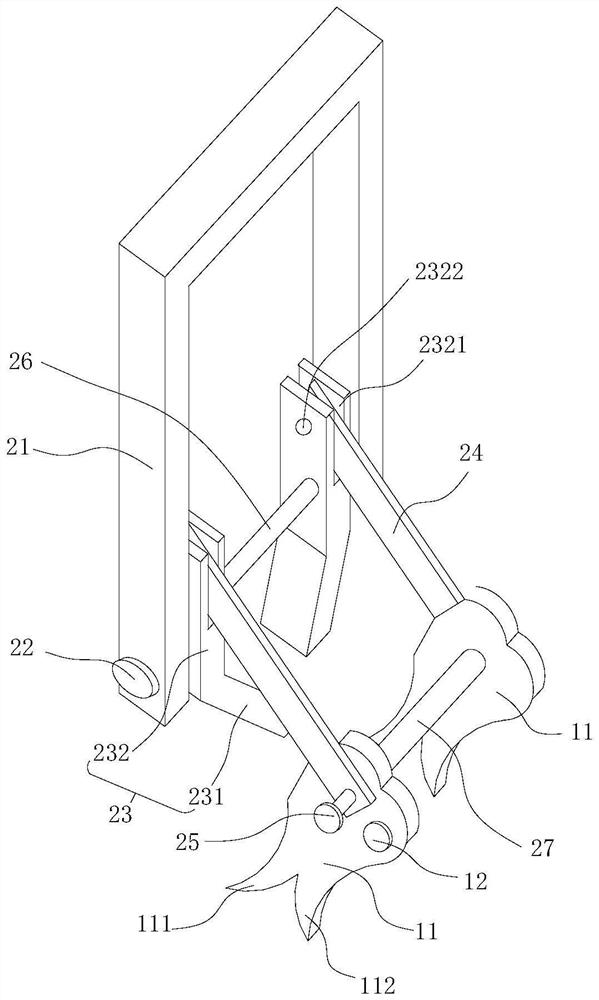
The chain cleaning device comprises a guide assembly and a scraping assembly rotationally installed on the guide assembly, the scraping assembly comprises a plurality of scraping plates and balance weight pieces arranged on the scraping plates, the scraping plates are provided with first scraping parts and second scraping parts, the balance weight pieces can act on the scraping plates downwards, and the first scraping parts and the second scraping parts are arranged on the scraping plates. The first scraping parts of the scraping plates are tilted in the opposite direction of the running of the chain, the arc end faces of the inner chain plates and / or the arc end faces of the outer chain plates on the chain can abut against the first scraping parts, and the scraping plates can be driven by the first scraping parts to swing along with the corresponding inner chain plates and / or the corresponding outer chain plates; the guide assembly can act on the two symmetrical inner chain plates or the two symmetrical outer chain plates on the chain so as to play a role in guiding the scraping assembly. According to the chain, the effect of cleaning the viscous pulverized coal on the arc end faces of the inner chain plates and / or the arc end faces of the outer chain plates on the chain can be achieved, and therefore the abrasion problem caused by the fact that the viscous pulverized coal is not cleaned in time is avoided.

Description

technical field [0001] The invention belongs to the technical field related to chains, in particular to a chain cleaning device. Background technique [0002] Chains, generally metal links or rings, are mostly used for mechanical transmission and traction. In the process of producing coke, enterprises usually need to use large-scale chain sprocket transmission mechanism, so as to use chain to drive parts to reciprocate according to the needs of use. For example, in the process of hammering coal powder into briquettes, it is usually necessary to use large The special chain sprocket drives the hammering roller, and rolls back and forth on the upper end of the final formed briquette to further compact the coal powder on the upper surface of the briquette. [0003] as attached figure 1 As shown, the chain 200 usually includes a plurality of inner chain plates 203 and outer chain plates 204 arranged at intervals in sequence, wherein the inner chain plates 203 are arranged on th...

Claims


Application Information

Patent Timeline
IPC IPC(8): B21L15/00B08B1/02
CPCB21L15/00B08B1/20B08B1/165
Inventor 武根林孔吉昌李文祥
Owner 河北华丰能源科技发展有限公司
Learn More