
Current-limiting reactor structure for limiting overcurrent of power system

A current-limiting reactor, power system technology, applied in emergency protection circuit devices for limiting overcurrent/overvoltage, transformer/reactor installation/support/suspension, transformer/inductor components, etc. , Triggering current disassembly and replacement operation, etc., to achieve the effect of strengthening the inductive reactance, shortening the maintenance time, and expanding the scope of application

Active Publication Date: 2021-04-23
山东泰开电力电子有限公司
View PDF11 Cites 0 Cited by
  • Summary
  • Abstract
  • Description
  • Claims
  • Application Information

AI Technical Summary

Problems solved by technology

[0004] Aiming at the deficiencies in the use of the current-limiting reactor structure for limiting overcurrent in the existing power system proposed in the background technology, the present invention provides a current-limiting reactor structure for limiting overcurrent in the power system, which can The advantage of changing the number of coils solves the problem of cumbersome operation caused by the need to disassemble and replace the original equipment when changing the peak value of the trigger current

Method used


Image

  • Current-limiting reactor structure for limiting overcurrent of power system
  • Current-limiting reactor structure for limiting overcurrent of power system
  • Current-limiting reactor structure for limiting overcurrent of power system

Examples


Embodiment Construction

[0026] The following will clearly and completely describe the technical solutions in the embodiments of the present invention with reference to the accompanying drawings in the embodiments of the present invention. Obviously, the described embodiments are only some, not all, embodiments of the present invention. Based on the embodiments of the present invention, all other embodiments obtained by persons of ordinary skill in the art without making creative efforts belong to the protection scope of the present invention.

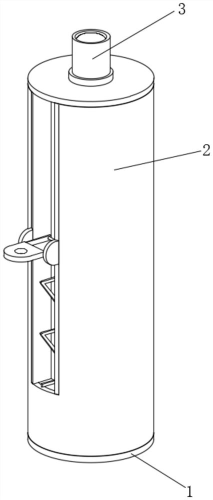
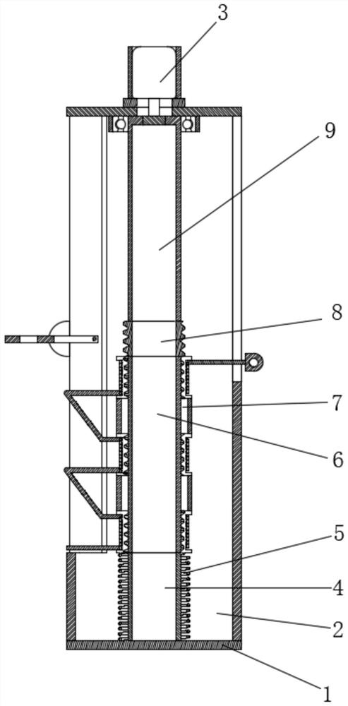
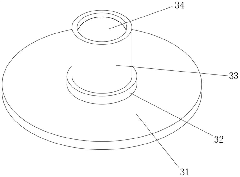
[0027] see Figure 1-9, a current-limiting reactor structure for limiting overcurrent in a power system, including a base 1, and a limit device 2 is fixedly installed on the top of the base 1 at an outer position. The limit device 2 includes a shell 21, and one side of the outer surface of the shell 21 is fixed The guide rail frame 22 is installed, and the bottom of the guide rail frame 22 is provided with a strip hole and the contact bracket 73 and the contac...


PUM


Abstract

The invention belongs to the technical field of line protection, and discloses a current-limiting reactor structure for limiting overcurrent of a power system. The current-limiting reactor structure comprises a base; a limiting device is fixedly mounted at the upper top of the outer side of the base; when the reactance device continues to rise, the reactance device cannot continue to contact with an elastic contactor due to over-high top end of a contact bracket, at the moment, the elastic contactor can be separated from the contact bracket, can be quickly reset under the action of the elastic force of the elastic contactor and contacts with a contact bracket II, so that the circuit breaking time in a contact replacement process of the elastic contactor is shortened, and the stability of the device is further improved; when the elastic contactor contacts with the contact bracket II, at the moment, an reactor II and a reactor I are connected to a line together, so that an inductive reactance effect is improved, the effect of adjusting the inductive reactance of the reactor without dismounting and mounting processes is achieved, and the problem of tedious operation caused by the fact that a traditional reactor needs to be dismounted and mounted when needing to be adjusted can be solved; and the practicability of the device is improved.

Description

technical field [0001] The invention relates to the technical field of line protection, in particular to a current-limiting reactor structure for limiting overcurrent in a power system. Background technique [0002] The current-limiting reactor is a very common electrical component, usually used in the power network, the reactor is essentially an air-core coil without magnetic material, it can be arranged in vertical, horizontal and zigzag three assembly forms according to the requirements, in the circuit When a short circuit occurs in the middle, a large short-circuit current will be generated, and the reactor increases the short-circuit impedance through its own inductance, limits the short-circuit current, and avoids the damage of the electrical components connected to the line by high current. In addition, the reactance The voltage drop on the transformer is relatively large, so it also plays a role in maintaining the voltage level of the bus, making the voltage fluctuat...

Claims


Application Information

Patent Timeline
IPC IPC(8): H01F27/06H01F27/29H01F27/30H02H9/02
CPCH02H9/021H01F27/06H01F27/306H01F27/29
Inventor 屈汉明
Owner 山东泰开电力电子有限公司
Learn More