Supercharge Your Innovation With Domain-Expert AI Agents!

Anti-cavitation high-lift centrifugal pump impeller

A centrifugal pump impeller and high-lift technology, which is applied in the direction of pumps, pump components, non-variable pumps, etc., can solve the problems of centrifugal pump head reduction, etc., and achieve the improvement of output head, the reduction of cavitation volume, and the expansion of high-efficiency operating areas Effect

Active Publication Date: 2017-07-11
LANZHOU UNIVERSITY OF TECHNOLOGY
View PDF10 Cites 9 Cited by
  • Summary
  • Abstract
  • Description
  • Claims
  • Application Information

AI Technical Summary

Problems solved by technology

[0004] In order to solve the problem that the head of the centrifugal pump decreases due to the rapid drop of the fluid pressure inside the impeller as the cavitation intensity increases during the operation of the centrifugal pump, the present invention proposes a brand new anti-cavitation high-lift centrifugal pump impeller

Method used


Image

  • Anti-cavitation high-lift centrifugal pump impeller
  • Anti-cavitation high-lift centrifugal pump impeller
  • Anti-cavitation high-lift centrifugal pump impeller

Examples


Embodiment Construction

[0019] The technical solutions of the present invention will be described in detail below in conjunction with the accompanying drawings.

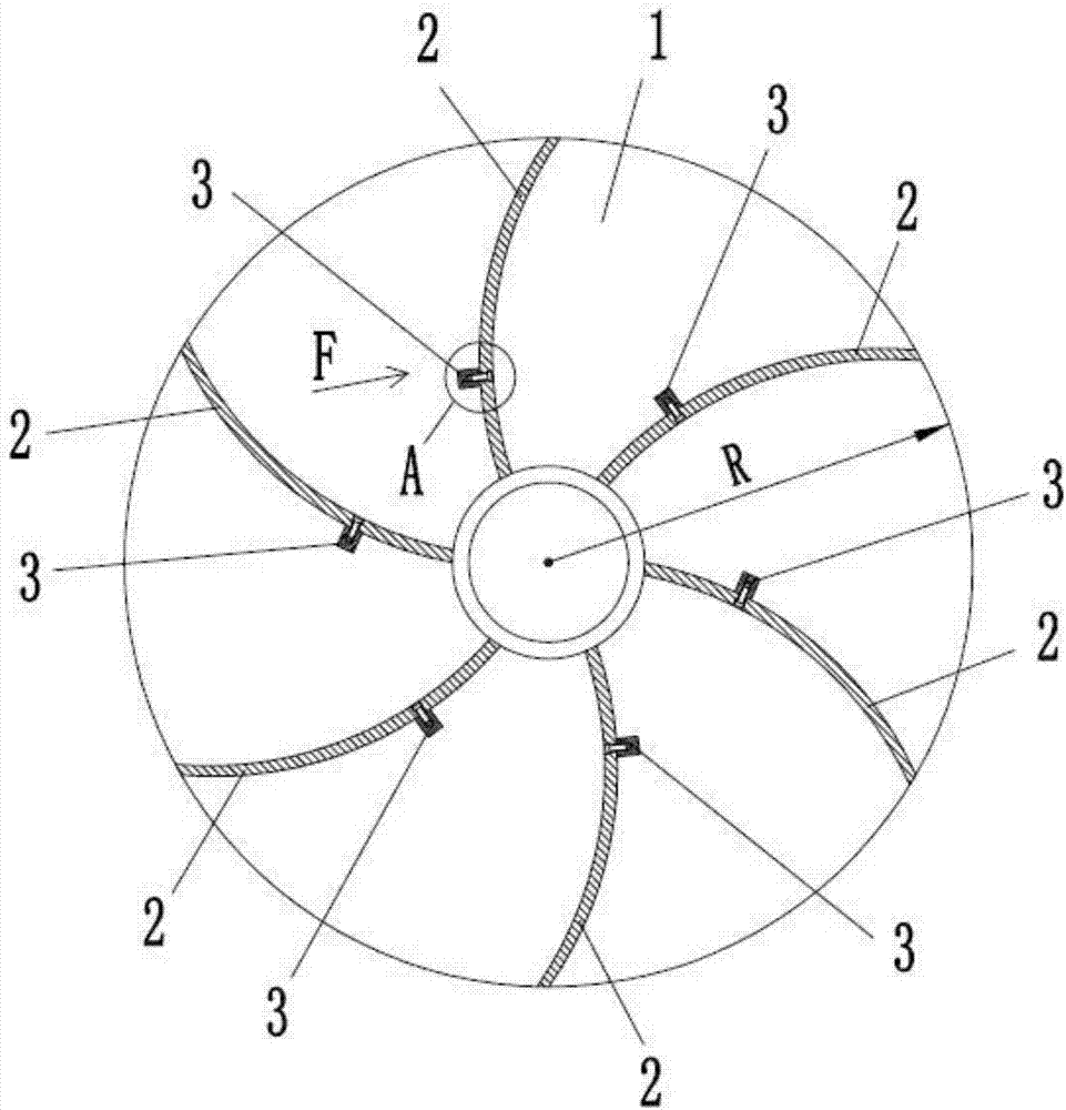
[0020] combine figure 1 , figure 2 and image 3 As shown, the anti-cavitation high-lift centrifugal pump impeller of the present invention includes a cover plate 1 , a blade 2 and a boss 3 , wherein the boss 3 is fixedly connected to the working surface 21 of the blade 2 . Based on the central axis of the impeller, the position of the boss 3 on the working surface 21 is: radial position r=K r ×R; the axial position is 1 / 2 of the axial section line 211 on the working surface 21 at the radial position r. The external structure dimension of the boss 3 is: the length dimension a=K of the cross section a ×R; the width dimension of the cross section b=K b ×R; the height dimension h=K from the top of the boss 3 to the working surface 21 h ×R. Among them, R is the radius of the impeller; K r is the radial position coefficient, K r =0.20~0...


PUM


Abstract

The invention relates to an anti-cavitation high-lift centrifugal pump impeller. The brand new anti-cavitation high-lift centrifugal pump impeller is disclosed in order to solve the problem that the lift of a centrifugal pump is reduced due to the fact that the pressure of fluid in an impeller is rapidly reduced along with the increase of the cavitation intensity in the operation process of the centrifugal pump. The anti-cavitation high-lift centrifugal pump impeller comprises blades, a cover plate and bosses. Each boss is fixedly connected with the corresponding blade and located on one side of the working surface of the blade. According to the anti-cavitation high-lift centrifugal pump impeller disclosed by the invention, the structure is simple; machining is convenient; and in addition, the boss structures are arranged on the working surfaces of the blades, so that an improvement effect is achieved on a low-pressure area and the adverse pressure gradient in an impeller runner, then an inhibiting effect is achieved on the void volume produced when cavitation occurs to a centrifugal pump, and thus the purposes of increasing the lift value of the centrifugal pump under the cavitation state and expanding the efficient operation area of the centrifugal pump under the cavitation state are achieved.

Description

technical field [0001] The invention relates to an impeller, in particular to an anti-cavitation high lift centrifugal pump impeller. Background technique [0002] A centrifugal pump is a pump that relies on the centrifugal force generated by the rotation of the impeller to transport fluid. Before the centrifugal pump is started, the pump casing and the suction pipe are filled with fluid, and then the motor is started, so that the pump shaft drives the impeller and the fluid to rotate at a high speed. It flows into the pressure water pipeline of the centrifugal pump, and finally the fluid is output from the pressure water pipeline. With the continuous discharge of the fluid inside the impeller, a low-pressure area is gradually formed at the center of the impeller, even reaching a vacuum. At this time, the fluid at the inlet of the centrifugal pump flows into the impeller continuously through the suction pipe under the action of atmospheric pressure, and is then thrown by th...

Claims


Application Information

Patent Timeline
IPC IPC(8): F04D29/24
CPCF04D29/242
Inventor 赵伟国赵国寿王桂鹏夏添马亮亮
Owner LANZHOU UNIVERSITY OF TECHNOLOGY
Features
  • R&D
  • Intellectual Property
  • Life Sciences
  • Materials
  • Tech Scout
  • Unparalleled Data Quality
  • Higher Quality Content
  • 60% Fewer Hallucinations
Learn More