
Screw rod transmission mechanism

A screw drive, screw shaft technology, applied in the direction of brake actuators, gear shifting mechanisms, mechanical equipment, etc., can solve the problems of complex braking structure, no screw shaft, poor braking effect, etc., to ensure The effect of transmission accuracy

Active Publication Date: 2017-07-11
苏州科米隆机电有限公司
View PDF24 Cites 1 Cited by
  • Summary
  • Abstract
  • Description
  • Claims
  • Application Information

AI Technical Summary

Problems solved by technology

[0002] The existing screw devices generally do not have a structure that can brake the rotation of the screw shaft. Even if some screw devices are equipped with a braking structure, the braking effect is more or less poor and the braking structure is complicated. And other issues

Method used


Image

  • Screw rod transmission mechanism
  • Screw rod transmission mechanism
  • Screw rod transmission mechanism

Examples


Embodiment Construction

[0025] In order to understand the above-mentioned purpose, features and advantages of the present invention more clearly, the present invention will be further described in detail below in conjunction with the accompanying drawings and specific embodiments. It should be understood that these examples are used to illustrate the present invention and not to limit the scope of the present invention. The implementation conditions used in the examples can be further adjusted according to the conditions of specific manufacturers, and the implementation conditions not indicated are usually the conditions in routine experiments. In the following description, many specific details are set forth in order to fully understand the present invention. However, the present invention can also be implemented in other ways different from those described here. Therefore, the protection scope of the present invention is not limited by the specific details disclosed below. EXAMPLE LIMITATIONS.

[...


PUM


Abstract

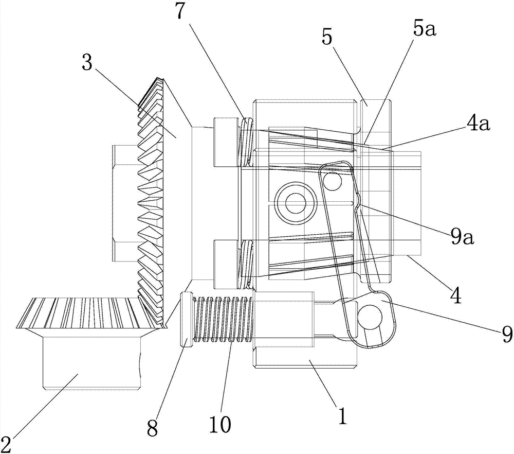
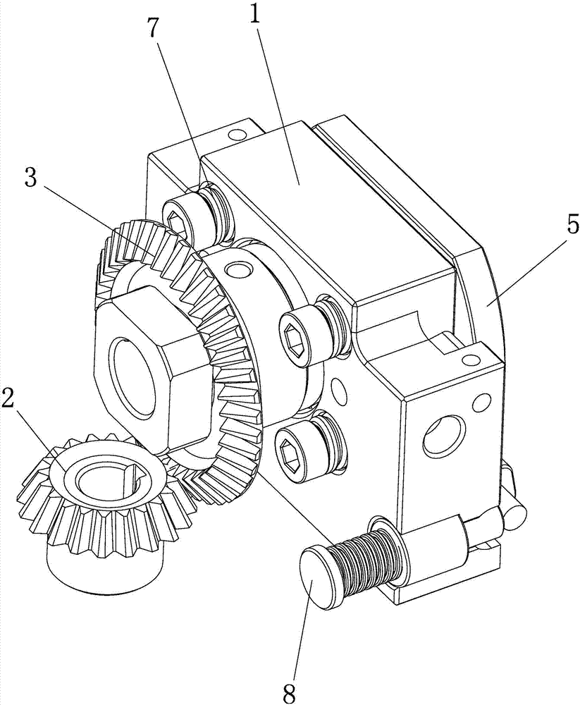
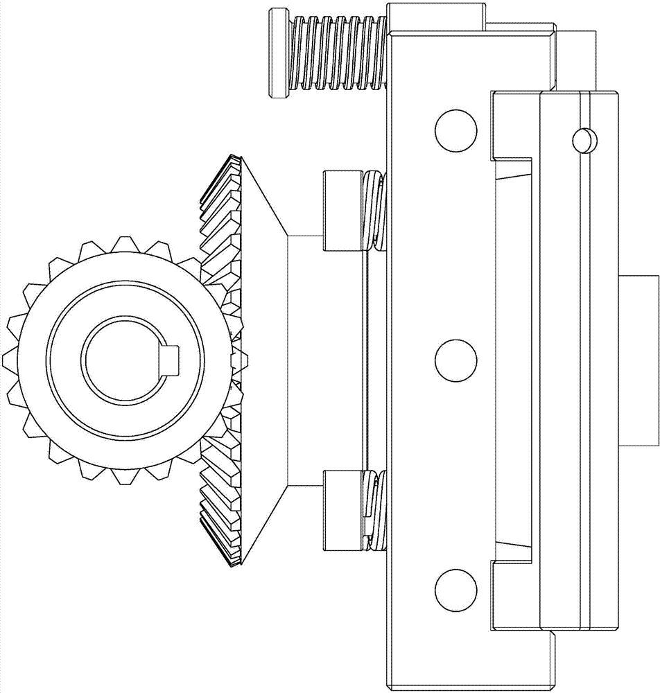
The invention discloses a screw rod transmission mechanism. The screw rod transmission mechanism comprises a screw rod shaft and a screw rod nut which are in threaded fit and further comprises a driven bevel gear, a driven bevel gear, a shaft sleeve, a brake disc, a guide shaft, a compressed spring, a brake pin and a drive rod. The driven bevel gear is connected with a drive motor. The driven bevel gear is in meshing connection with the driven bevel gear, and the driven bevel gear and the screw rod shaft are fixed coaxially. The shaft sleeve is fixed to the screw rod shaft coaxially and is provided with a conical peripheral face. The brake disc is movably arranged outside the shaft sleeve in a sleeving mode. The guide shaft can penetrate in a screw rod seat axially movably and is fixedly connected with the brake disc. The compressed spring is connected between the screw rod seat and the brake disc and applies elastic force to the brake disc, and the elastic force makes the brake disc axially press on the conical peripheral face of the shaft sleeve. The brake pin can penetrate in the screw rod seat axially movably. One end of the drive rod is connected to the screw rod seat pivotally, the other end of the drive rod is in contact fit with the brake pin, and the brake disc tightly presses in the middle of the drive rod. Through the screw rod transmission mechanism, rotation of the screw rod shaft can be braked stably, and then transmission precision of the screw rod is ensured.

Description

technical field [0001] The invention relates to a screw drive mechanism. Background technique [0002] The existing screw devices generally do not have a structure that can brake the rotation of the screw shaft. Even if some screw devices are equipped with a braking structure, the braking effect is more or less poor and the braking structure is complicated. And other issues. [0003] This application is hereby derived. Contents of the invention [0004] The object of the present invention is: to solve the above problems, propose a screw drive mechanism with braking function, which can perform stable braking on the rotation of the screw shaft, thereby ensuring the transmission accuracy of the screw. [0005] The technical solution of the present invention is: a screw drive mechanism, comprising a threaded screw shaft and a screw nut, wherein the screw shaft is rotatably connected to the screw seat, and also includes: [0006] The active bevel gear is connected with the d...

Claims


Application Information

Patent Timeline
IPC IPC(8): F16D65/18F16D121/14
CPCF16D65/18F16D2121/14
Inventor 帅陆军
Owner 苏州科米隆机电有限公司
Learn More