Magneto-rheological hydraulic brake executing device for electric vehicles

A magneto-rheological fluid and actuator technology, applied in electric vehicles, electric braking systems, vehicle components, etc., can solve problems such as limited equipment life and safety of electricity use, long magnetic pole switching time, and inability to apply to automobiles, etc., to achieve The effect of shortening the braking distance of the car, continuously controlling the braking hydraulic pressure, and simplifying the processing of parts

Active Publication Date: 2013-04-24
TSINGHUA UNIV
View PDF9 Cites 14 Cited by
  • Summary
  • Abstract
  • Description
  • Claims
  • Application Information

AI Technical Summary

Problems solved by technology

There is a small amount of research on magnetorheological fluid brakes in China. The patented technology (200910099608.3) that has been published at present proposes the general structure of phase change brakes, but the electrorheological fluid material is far from meeting the braking force requirements, and it does not consider magnetorheological fluid as a system. When the liquid is moving, the generation of an external trigger signal (magnetic field)
The structure of the magneto-rheological fluid brake designed by the patented technology (03141793.0) is variable, but the electromagnetic coil is supported by the inner cylinder, which greatly reduces the ability of the coil to generate a magnetic field
At the same time, when the thickness of the brake disc is increased, the magnetic resistance becomes larger, the magnetic field drops rapidly, and the braking torque drops sharply, so it cannot be applied to automobiles.
The patented technology (200410084576.7) is a brake with a built-in coil, which has the advantages of large torque, etc. However, due to the working state of the magnetorheological fluid, the coil will be worn and the power supply is inconvenient, so the life of the equipment and the safety of power consumption are relatively limited.
The patented technology (201020620713.5) uses permanent magnets as the magnetic field source, which has the characteristics of energy saving. However, when the braking and non-braking states are switched, the magnets need to be operated. The operating mechanism is complex and the magnetic pole switching time is long, which cannot meet the vehicle braking requirements.

Method used


Image

  • Magneto-rheological hydraulic brake executing device for electric vehicles
  • Magneto-rheological hydraulic brake executing device for electric vehicles
  • Magneto-rheological hydraulic brake executing device for electric vehicles

Examples


Embodiment Construction

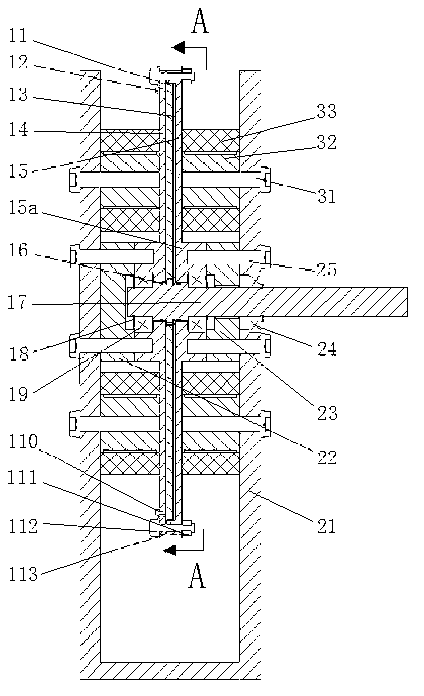
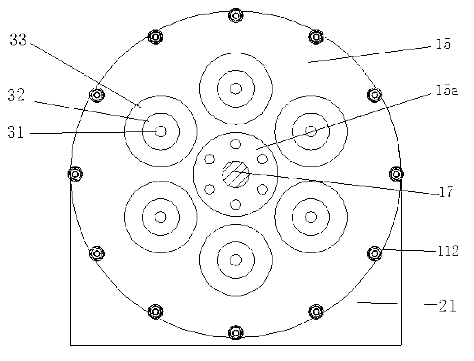
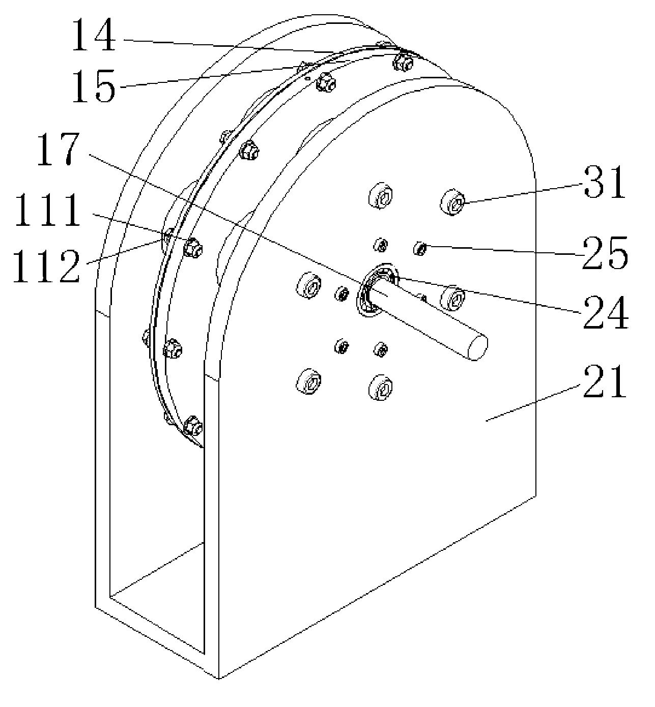
[0016] The magneto-rheological fluid brake actuator for electric vehicles proposed by the present invention has a structure such as figure 1 As shown, it mainly includes brake disc 11, magnetorheological fluid 13, left housing 14, right housing 15, electromagnet core 32, electromagnetic coil 33, left connecting disc 22, right connecting disc 23 and U-shaped support plate 21. Such as figure 2 As shown in the AA sectional view of the left housing 14 and the right housing 15, the left housing 14 and the right housing 15 are connected by housing connecting nuts 111 and The casing connecting bolts 112 are relatively fixed to form a casing, and the brake disc 11 and the magneto-rheological fluid 13 are placed in the casing. The center of the left shell 14 and the right shell 15 that make up the shell is a boss, and the shell is supported on the U-shaped support plate 21 by the left connecting plate 22, the right connecting plate 23 and the shell supporting bolt 25 at the central b...


PUM


Abstract

The invention relates to a magneto-rheological hydraulic brake executing device for electric vehicles and belongs to the technical field of electric vehicles. The magneto-rheological hydraulic brake executing device comprises a driving shaft, a brake disk, magneto-rheological liquid, a shell, an electromagnetic coil, connecting plates and a support structure from the inside to the outside. The driving shaft and the brake disk are fixedly connected with a spline and transmit torque to wheels. A left shell piece and a right shell piece are integrally connected through bolts, the brake disk is horizontally disposed in the shell, and the magneto-rheological liquid is filled into the shell. The electromagnetic coil takes an iron core as a support, is limited and fixed by bolts distributed on the support and fits with the outer surface of the shell to form a magnetic loop. The support structure comprises a left portion and a right portion, is fixedly connected with a car body, transmits brake force to the vehicle body, supports the electromagnetic coil through bolts and fixes the brake structure by bolts. The magneto-rheological hydraulic brake executing device is simple and compact in structure, accordant with requirements of the vehicles, capable of setting pressure at millisecond magnitude and convenient to adjust and can meet the requirements for brake strength of the vehicles.

Description

technical field [0001] The invention relates to a magneto-rheological fluid brake actuator for an electric vehicle, which belongs to the technical field of automobile manufacturing. Background technique [0002] Traditional automobiles use a hydraulic brake system, and its brake actuator includes a brake pedal, a vacuum booster, a master cylinder, four sets of disc brakes, a hydraulic control unit, an electronic control unit, the master cylinder and the hydraulic control unit. Brake lines and brake lines connecting the hydraulic control unit to the individual wheel brakes. In the traditional car braking system, after the driver touches the brake pedal, as the brake pedal moves forward, the vacuum booster uses the engine back pressure to boost and push the master cylinder piston forward. When the gap in the master cylinder and the brake gap are eliminated Thereafter, brake fluid pressure is gradually generated in the brakes of the respective wheels. Usually there is a time ...

Claims


Application Information

Patent Timeline
Patent Type & Authority Applications(China)
IPC IPC(8): B60L7/26
Inventor 马良旭于良耀朱先民宋健
Owner TSINGHUA UNIV
Why Eureka
Try Eureka