Simple current collector return device

A current collector, a simple technology, applied in the direction of current collectors, power collectors, transportation and packaging, etc., can solve the problems of non-adjustable shoe-off position, fixed and non-adjustable shoe-off position of current collector, and large friction

Pending Publication Date: 2017-07-14
QINGDAO METRO GRP CO LTD +1
View PDF7 Cites 5 Cited by
  • Summary
  • Abstract
  • Description
  • Claims
  • Application Information

AI Technical Summary

Problems solved by technology

Its disadvantages are as follows: firstly, the recovery device and the driven lever of the current receiver perform sliding frictional movement, the friction force is large, and the operator is laborious to operate; secondly, the retraction control lever on the recovery device The length is fixed and not adjustable, resulting in a fix...

Method used


Image

  • Simple current collector return device
  • Simple current collector return device
  • Simple current collector return device

Examples


Embodiment 1

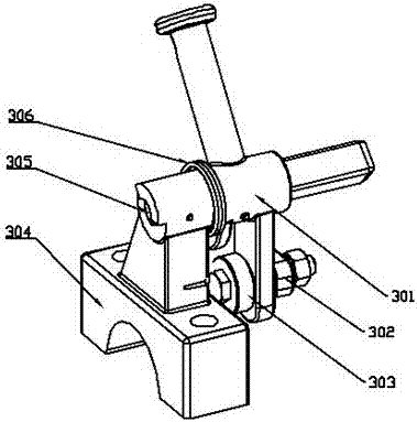
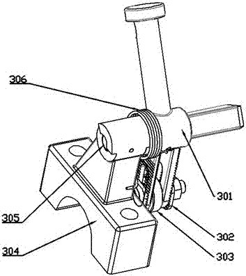
[0019] Embodiment 1: as figure 1 , 2 , 3, the recovery device 203 includes a retraction control rod 301, an adjustment device 302, a rolling device 303, a retraction pressure plate 304, a connecting pin 305, and a torsion spring 306.

[0020] Such as figure 1 , 2 As shown in , 3, the recovery device 203 includes a hinged assembly of the retraction control rod 301 and the retraction pressure plate 304 through a connecting pin 305 .

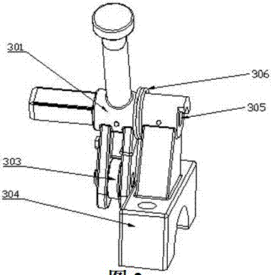
[0021] During normal operation, such as Figure 4 As shown, the recovery device 203 will return the retraction control lever 301 to the initial position opposite to the retraction pressure plate 304 after being out of contact with the driven lever 201 on the current collector through the torsion spring 306, and the current collector Sliding shoe 202 is in the working position.

[0022] When the train needs to take off the boots of the current collector, such as Figure 5 As shown, the retraction control lever 301 performs a rolling friction m...


PUM


Abstract

The invention relates to a simple current collector return device which is mainly used for quickly assisting a current collector to conduct operation of getting rid of a third rail when a subway vehicle needs power-off and shoe taking off. The return device (203) comprises a rollback control rod (301), a rolling device (303), a rollback pressing plate (304), a connecting pin shaft (305) and a torsion spring (306); the rollback control rod (301) and the rollback pressing plate (304) are connected through the connecting pin shaft (305); the rolling device (303) is connected with the rollback control rod (301); the torsion spring (306) is mounted on the connecting part of the rollback control rod (301) and the rollback pressing plate (304); and the rolling device (303) on the rollback control rod (301) and a driven pushing rod (201) of the current collector conduct rolling and friction motion. The return device can be widely applied to in the shoe taking off operation of the third rail current collector.

Description

technical field [0001] The invention relates to a simple recovering device for a current receiver, which is suitable for the recovering device when the current receiver is detached from the third rail. Background technique [0002] In the current recovery device of the current receiver, the recovery device of the current receiver disclosed in Chinese Patent Application No. CN 201020636576 and CN201020636590, through the sliding friction movement of the retraction control rod on the recovery device and the driven lever of the current receiver, Realize the separation of the locking current collector or the current collector shoe from the third rail. Its disadvantages are as follows: firstly, the recovery device and the driven lever of the current receiver perform sliding frictional movement, the friction force is large, and the operator is laborious to operate; secondly, the retraction control lever on the recovery device The length is fixed and not adjustable, resulting in a...

Claims


Application Information

Patent Timeline
IPC IPC(8): B60L5/39
CPCB60L5/39
Inventor 陈萍程卫群杨开伟万理
Owner QINGDAO METRO GRP CO LTD
Why Eureka
Try Eureka