Vehicle bumper

A technology for bumpers and vehicles, applied in the field of vehicle bumpers, can solve the problems of low safety, poor buffering and energy-absorbing effect of bumpers, etc., and achieve the effects of fast response speed, superior buffering protection performance, and high energy-absorbing efficiency

Inactive Publication Date: 2017-07-14
NANJING UNIV OF AERONAUTICS & ASTRONAUTICS
View PDF5 Cites 1 Cited by
  • Summary
  • Abstract
  • Description
  • Claims
  • Application Information

AI Technical Summary

Problems solved by technology

[0004] Technical problem to be solved: the technical problem to be solved by this application is the technical problems such as poor buffering energy absorption effect and low safety of the prior art bumper. In order to make up for the deficiencies of the prior art, the present invention aims to p

Method used


Image

  • Vehicle bumper
  • Vehicle bumper
  • Vehicle bumper

Examples


Embodiment 1

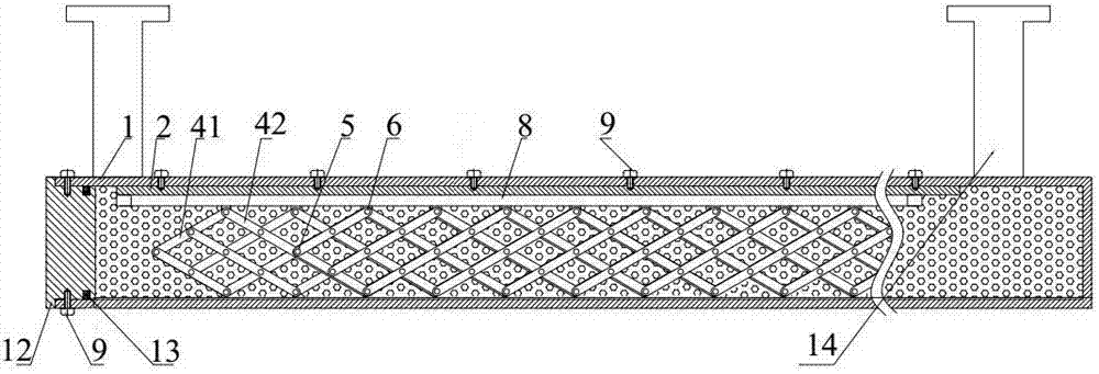
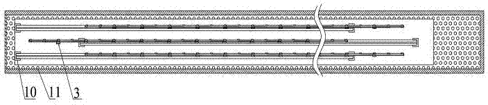
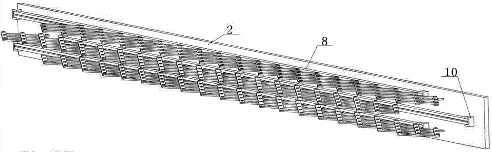
[0026] Such as figure 1 , figure 2 , image 3 and Figure 4 As shown, a vehicle bumper includes a packaging layer 1, a mounting plate 2, a fixing ring 3, a forward rod 41, a reverse rod 42, a short shaft 5, a long shaft 6, a T-shaped slider 7, a guide rail 8, a fastening Screw 9, cover 10, STF11, end cap 12, sealing ring 13, anti-collision beam support frame 14 and shear synergistic device, said STF11 is formed by stirring and mixing silicon dioxide nanoparticles and PEG200, and said The micropore diameter of the silicon nanomaterial is 180nm; the encapsulation layer 1 is a metal member with an unclosed end and a cavity inside, and the interior of the encapsulation layer 1 is filled with STF11; the end cap 12 is set inside the unenclosed end of the encapsulation layer 1 The anti-collision beam support frame 14 is located on the outer surface of the packaging layer 1; the outer end surface of the mounting plate 2 is connected with the inner surface of the packaging layer 1 ...

Embodiment 2

[0035] Such as figure 1 , figure 2 , image 3 and Figure 4 As shown, a vehicle bumper includes a packaging layer 1, a mounting plate 2, a fixing ring 3, a forward rod 41, a reverse rod 42, a short shaft 5, a long shaft 6, a T-shaped slider 7, a guide rail 8, a fastening Screw 9, cover 10, STF11, end cap 12, sealing ring 13, anti-collision beam support frame 14 and shear synergistic device, said STF11 is formed by stirring and mixing silicon dioxide nanoparticles and PEG200, and said The micropore diameter of the silicon nanomaterial is 220nm; the encapsulation layer 1 is a metal member with an unclosed end and a cavity inside, and the interior of the encapsulation layer 1 is filled with STF11; the end cap 12 is set inside the unenclosed end of the encapsulation layer 1 The anti-collision beam support frame 14 is located on the outer surface of the packaging layer 1; the outer end surface of the mounting plate 2 is connected with the inner surface of the packaging layer 1 ...

Embodiment 3

[0044] Such as figure 1 , figure 2 , image 3 and Figure 4 As shown, a vehicle bumper includes a packaging layer 1, a mounting plate 2, a fixing ring 3, a forward rod 41, a reverse rod 42, a short shaft 5, a long shaft 6, a T-shaped slider 7, a guide rail 8, a fastening Screw 9, cover 10, STF11, end cap 12, anti-collision beam support frame 14 and shear synergistic device, described STF11 is formed by stirring and mixing silicon dioxide nanoparticles and PEG200, the silicon dioxide nanomaterial The micropore diameter is 200nm; the encapsulation layer 1 is a metal member with an unclosed end and a cavity inside, and the interior of the encapsulation layer 1 is filled with STF11; the end cap 12 is set inside the unenclosed end of the encapsulation layer 1; the anti-collision beam The support frame 14 is arranged on the outer surface of the packaging layer 1; the outer end surface of the mounting plate 2 is connected with the inner surface of the packaging layer 1 through fa...


PUM

PropertyMeasurementUnit
Pore diameteraaaaaaaaaa

Abstract

The invention discloses a vehicle bumper. The vehicle bumper comprises a packaging layer, a mounting plate, a fixing ring, a forward lever, a reverse lever, a short rotating shaft, a long rotating shaft, a T-shaped sliding block, a guide rail, a fastening screw, an STF, an end cover, an anti-collision beam support frame and a shear effect increasing device. The vehicle bumper has the characteristic of superior cushion protection performance, can be widely applied the field of collision protection of vehicles to reduce the casualty rate of personnel and property loss. By combining STF and multi-link structure, the good energy absorption characteristic of the STF is used and the kinetic characteristic of a multi-link structure is also used so that when shock occurs, other STFs around are driven to participate in the energy consumption process, the utilization efficiency of the STFs is improved, and energy absorption efficiency of the STF is greatly improved. The STF has a sensitive and rapid response to the shear strain rate so that the bumper can make a high energy consumption response at the moment the bumper is shocked, the protective performance of the structure is improved and the complexity of the whole structure is reduced.

Description

technical field [0001] The invention belongs to the technical field of auto parts, and in particular relates to a vehicle bumper. Background technique [0002] The car bumper is a safety device that absorbs and slows down the external impact and protects the front and rear of the car body. The existing car bumper is generally an arc-shaped shell structure made of steel plate stamping. During a collision, the deformation of the metal is used to absorb the collision energy. To ensure the safety of the occupants of the vehicle. However, the existing bumper absorbs and consumes the collision energy only by the deformation of the shell, and the effect of buffering and absorbing energy is not ideal, and it is difficult to minimize the magnitude of the collision force, which greatly weakens the safety of the vehicle. [0003] The present invention is a new type of bumper structure utilizing the combination of multi-link structure and STF liquid. STF liquid is a new type of intel...

Claims


Application Information

Patent Timeline
IPC IPC(8): B60R19/18B60R19/20
CPCB60R19/18B60R19/20B60R2019/1806
Inventor 赵鹏陈前赵帅
Owner NANJING UNIV OF AERONAUTICS & ASTRONAUTICS
Why Eureka
Try Eureka