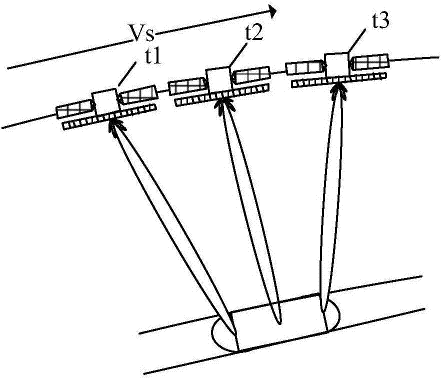
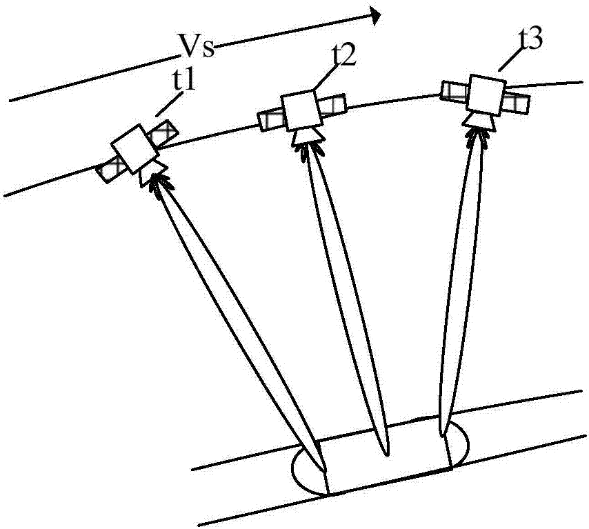
Synthetic aperture radar imaging method and device
A technology of synthetic aperture radar and imaging method, which is applied in the field of radar, and can solve the problems of low mechanical scanning speed and difficulty in realizing sliding spotlight imaging, etc.
- Summary
- Abstract
- Description
- Claims
- Application Information
AI Technical Summary
Problems solved by technology
Method used
Image
Examples
Embodiment 1
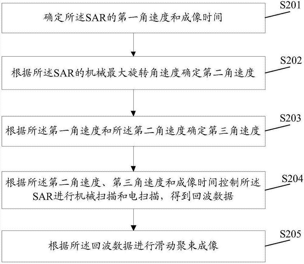
[0034] An embodiment of the present invention provides a synthetic aperture radar imaging method, which is applied to a synthetic aperture radar imaging device, figure 2 It is a schematic diagram of the implementation flow of a synthetic aperture radar imaging method according to an embodiment of the present invention, as figure 2 As shown, the method includes the following steps:
[0035] Step S201, determining the first angular velocity and imaging time of the SAR.
[0036] Here, the first angular velocity is the angular velocity of beam scanning in azimuth direction when the SAR performs sliding spotlight imaging.
[0037] The step S201 further includes:
[0038] Step S201a, collecting system parameters of the SAR;
[0039] Here, the system parameters of the SAR include but are not limited to: the operating speed of the SAR, the slant distance, the equivalent azimuth length of the antenna, and the azimuth beamwidth.
[0040] Step S201b, acquiring the preset imaging ar...
Embodiment 2
[0059] Based on the foregoing embodiments, an embodiment of the present invention further provides a synthetic aperture radar imaging method, which is applied to a synthetic aperture radar imaging device, and the synthetic aperture radar imaging device may be a processor in an actual implementation process. image 3 It is a schematic diagram of the implementation process of the second synthetic aperture radar imaging method of the present invention, as image 3 As shown, the method includes the following steps:
[0060] Step S301, determining the first angular velocity and imaging time of the SAR.
[0061] Here, the first angular velocity is the angular velocity of beam scanning in azimuth direction when the SAR performs sliding spotlight imaging.
[0062] The step S301 further includes:
[0063] Step S301a, collecting system parameters of the SAR;
[0064] Here, the system parameters of the SAR include but are not limited to: the operating speed of the SAR, the slant dista...
Embodiment 3
[0104] In order to better understand this embodiment, first introduce the composition and structure of the SAR satellite. Pic 4-1 It is a schematic diagram of the composition structure of the SAR satellite and the normal in-orbit flight state of the SAR satellite in Embodiment 3 of the present invention, such as Pic 4-1As shown, the SAR satellite is mainly composed of two parts: a satellite body 501 and an antenna 502 . In the normal on-orbit flight state, the SAR satellite body coordinate system is defined as: the origin of the coordinates is located at the center of mass O of the satellite; the X-axis points to the flight direction of the satellite, which is consistent with the antenna azimuth; the Z-axis is along the normal direction of the antenna array and points to the earth; The Y axis is perpendicular to the X and Z axes, which conforms to the right-hand rule. In the figure, OE points from the satellite to the center of the earth, and the angle between OE and OZ is ...
PUM
 Abstract
Description
Claims
Application Information
 - R&D
- Intellectual Property
- Life Sciences
- Materials
- Tech Scout
- Unparalleled Data Quality
- Higher Quality Content
- 60% Fewer Hallucinations
Browse by: Latest US Patents, China's latest patents, Technical Efficacy Thesaurus, Application Domain, Technology Topic, Popular Technical Reports.
© 2025 PatSnap. All rights reserved.Legal|Privacy policy|Modern Slavery Act Transparency Statement|Sitemap|About US| Contact US: help@patsnap.com


