
Demand response system and demand response method based on multi-tenancy technology

A demand response, multi-tenant technology, applied in information technology support systems, data processing applications, instruments, etc., can solve the problem of not being able to serve as a demand response public service platform, unable to support multiple implementation units at the same time, and unable to effectively integrate multiple demand responses Implement unit information resources and other issues to achieve accurate and reliable evaluation of demand response effects, accurate analysis of demand response potential, and avoid duplication of construction

Inactive Publication Date: 2017-07-14
STATE GRID CORP OF CHINA +4
View PDF0 Cites 11 Cited by
  • Summary
  • Abstract
  • Description
  • Claims
  • Application Information

AI Technical Summary

Problems solved by technology

[0011] In order to solve the above problems, the present invention provides a demand response system and method based on multi-tenant technology, which aims to solve the problem that the current demand response system can only be used for one energy service provider as a demand response implementation unit, and cannot support multiple implementation units at the same time Defects; or, it can only serve specific demand response implementation units, and cannot be used as a demand response public service platform, and cannot effectively integrate information resources of multiple demand response implementation units, and provide data analysis and prediction results.

Method used


Image

  • Demand response system and demand response method based on multi-tenancy technology
  • Demand response system and demand response method based on multi-tenancy technology
  • Demand response system and demand response method based on multi-tenancy technology

Examples


Embodiment Construction

[0075] In order to make the purpose, technical solution and advantages of the present invention clearer, the technical solution of the present invention will be described in detail below. Apparently, the described embodiments are only some of the embodiments of the present invention, but not all of them. Based on the embodiments of the present invention, all other implementations obtained by persons of ordinary skill in the art without making creative efforts fall within the protection scope of the present invention.

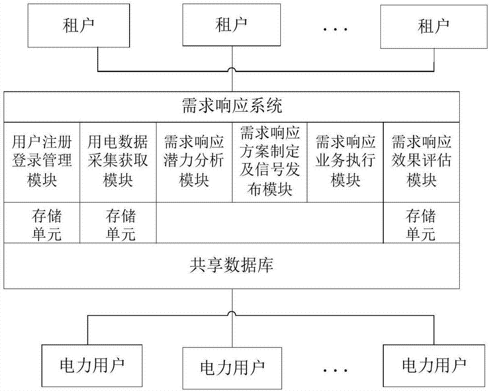
[0076] A demand response system based on multi-tenant technology. The demand response system interconnected with multiple tenants and power users includes: a user registration and login management module, a power consumption data collection and acquisition module, a demand response potential analysis module, and a demand response plan Development and signal release module, demand response business execution module and demand response effect evaluation module; am...


PUM


Abstract

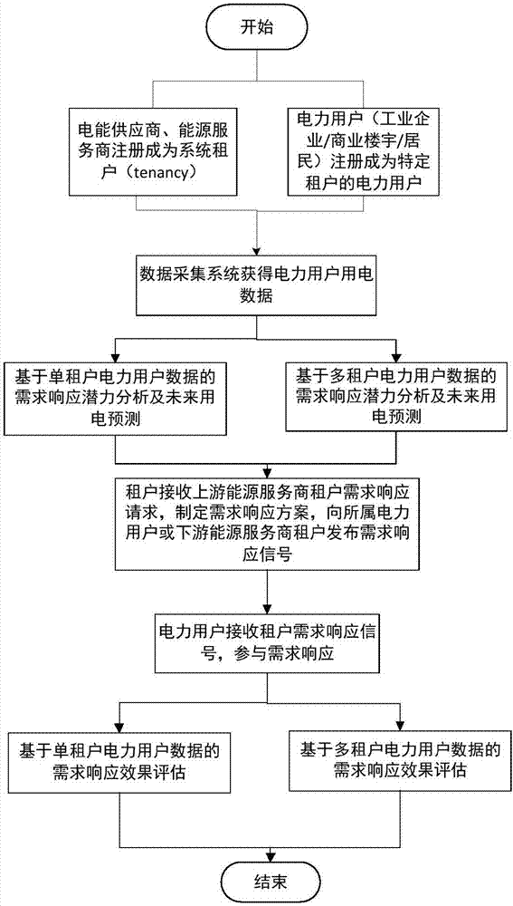
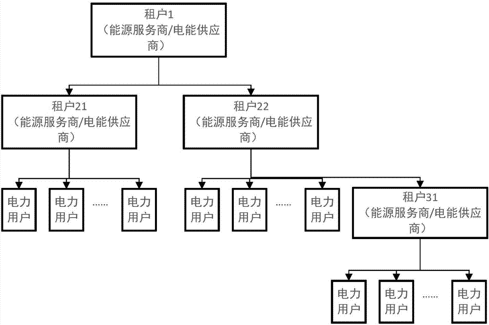
The invention provides a demand response system and a demand response method based on a multi-tenancy technology. Demand response implementation units, such as electricity providers and energy service providers are taken as tenants of a software system, and there are multiple electricity users under each tenant. Through a user registration and login management module, a power data acquisition module, a demand response potential analysis module, a demand response plan making and signal releasing module, a demand response service execution module and a demand response effect evaluation module contained in the demand response system, the demand response system has functions of power data acquisition, demand response potential analysis, demand response plan making and signal releasing, demand response service execution and demand response effect evaluation. The system and the method presented by the invention support multi-user operation. There is a cascade relationship between different tenants and electricity users. Demand response potential, demand response effect evaluation and other data analysis can be made based on data of multiple tenants. Therefore, address reuse and waste of resources are avoided.

Description

technical field [0001] The present invention relates to the field of demand response, in particular to a demand response system and method based on multi-tenancy technology. Background technique [0002] Power demand response means that power users voluntarily choose to reduce or increase the power load in a certain period of time according to the power price signal or incentive mechanism, so as to promote the balance of power supply and demand and protect the system. Safe and reliable operation. my country is in a stage of rapid economic development. In the long run, the national power supply and demand are generally tight, and power shortages are serious in some areas and during certain periods of time. Therefore, it is of great significance to use the elasticity of power demand to reduce the load during peak hours and alleviate the tense situation of power supply by tapping the load-scheduling capacity of the demand side. According to the nature of the response signal f...

Claims


Application Information

Patent Timeline
IPC IPC(8): G06Q10/06G06Q50/06
CPCG06Q10/06312G06Q10/06315G06Q10/06375G06Q50/06Y04S50/16
Inventor 孙明峰赵治文王尧邢广峰陈宋宋李德智郑君赵健一马聪聪段培冬韦古强李世豪何胜
Owner STATE GRID CORP OF CHINA
Learn More