Gas insulated power transmission line

A transmission line, gas insulation technology, applied in the direction of busbar/line layout, electrical components, busbar installation, etc., can solve the problems of affecting the normal use of conductors, conductor damage, and easy wear and tear of conductor installation, to achieve a good limit effect, Effect of preventing movement and increasing insulation

Inactive Publication Date: 2017-07-14
上海华东电器集团电气有限公司
View PDF6 Cites 6 Cited by
  • Summary
  • Abstract
  • Description
  • Claims
  • Application Information

AI Technical Summary

Problems solved by technology

[0004] However, when the line is used for a long time, the conductor will be damaged, so the conductor needs to be replaced. Since the conductor passes through the pot insulator, the pot insulator will play a good role in limiting the conductor , so the cooperation between the pot insulator a

Method used


Image

  • Gas insulated power transmission line
  • Gas insulated power transmission line
  • Gas insulated power transmission line

Examples


Embodiment 1

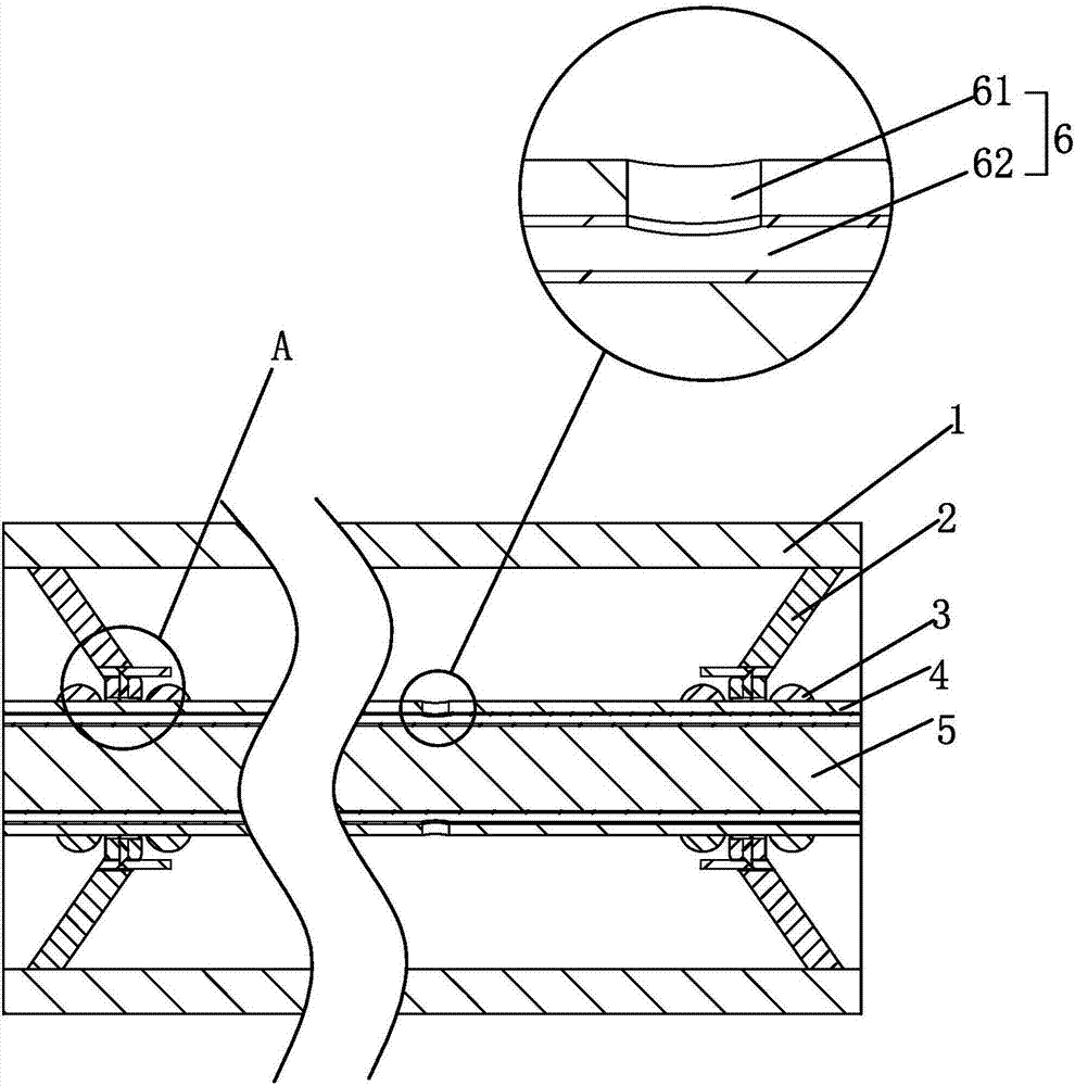
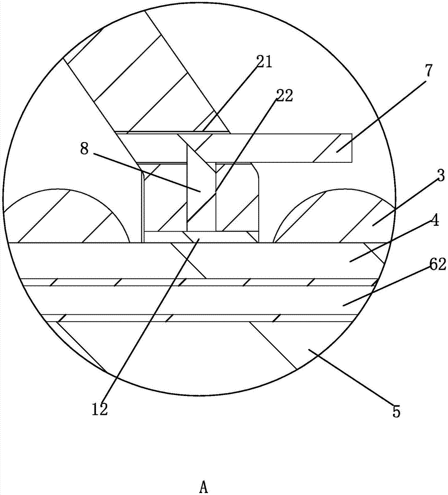
[0039] A gas insulated transmission line, with reference to figure 1 and figure 2, including several connected pipe units, the pipe unit includes a cylindrical shell 1 and pot insulators 2 fixed at both ends of the pipe unit, and a through hole 65 is provided on the pot insulator 2, and the penetration direction of the through hole 65 Parallel to the axial direction of the shell 1; a protective cover 4 is provided in the shell 1, and the protective cover 4 respectively passes through the through holes 65 on the two basin insulators 2. The shape of the through holes 65 is circular. The side wall of 65 is covered with a rubber strip, and the cross-sectional shape of the rubber strip is a circular ring arranged concentrically with the through hole 65 . At the end of the basin-type insulator 2 opposite to the housing 1, there are four extruding parts that squeeze the sealing strip 12 under the action of insulating compressed gas to increase the sealing between the sealing strip ...

Embodiment 2

[0045] A gas insulated transmission line, with reference to Figure 5 and Figure 6 The difference between the present embodiment and the first embodiment is that the clamping member 6 in the present embodiment includes a through hole 65 provided on the side wall of the protective cover 4, and the through hole 65 is sealed and slidable, and one end can be connected to the conductor 5 The clamping block 63 and the elastic member sleeved on the clamping block 63 with the side walls against each other; wherein, the elastic member is a spring 64, one end of the spring 64 is fixedly connected with the clamping block 63, and the other end is connected with the side wall of the through hole 65 Fixedly connected: one end of the clamping block 63 opposite to the protective sleeve 4 is covered with an elastic layer 10, the elastic layer 10 is made of rubber material, and several convex points 11 are arranged on the end of the elastic layer 10 opposite to the protective sleeve 4.

[004...


PUM


Abstract

The invention discloses a gas insulated power transmission line, including a plurality of connected pipeline units. Each pipeline unit comprises a shell, basin-type insulators arranged at two ends of the shell, a conductor passing through the basin-type insulators and insulated compression gas arranged between the shell and the conductor. The conductor is externally provided with a protective sleeve in a sleeving manner. The protective sleeve passes through the two basin-type insulators, and forms sealing cooperation with the basin-type insulators. The inner wall of the protective sleeve is provided with a clamping element which abuts against the conductor under the action of the insulated compression gas in the shell to achieve fixation of the conductor. When the conductor is assembled, the clamping element does not extrude the conductor, so that the phenomenon that the conductor is worn in the installation is avoided to a certain extent.

Description

technical field [0001] The present invention relates to a power transmission line, more specifically, it relates to a gas insulated power transmission line. Background technique [0002] At present, the traditional power transmission method is mainly composed of overhead lines and cable lines. Overhead lines have defects such as large line loss, being easily affected by environmental and climate factors, and consuming a lot of space and land resources. Although cable lines can be used for urban underground power transmission, but It also has the problems of large line loss and large capacitive current, and the cross-sectional area of ​​the current cable line has almost reached the limit of technology and economy, the carrying capacity is limited, and it must be equipped with a reactive power compensation device and a cooling system. [0003] In view of the above problems, the Chinese patent application No. 201420093317.X discloses a gas insulated electrical circuit, which in...

Claims


Application Information

Patent Timeline
IPC IPC(8): H02B1/20H02G5/06
CPCH02B1/202H02G5/063
Inventor 郑碎德
Owner 上海华东电器集团电气有限公司
Why Eureka
Try Eureka