Self-priming pump

A self-priming pump and pump body technology, applied in the direction of pump, pump control, driving pump, etc., can solve the problems of poor steam-water separation effect, damage to vacuum pump, inconvenience of changing the direction of input and output of self-priming pump, etc.

Inactive Publication Date: 2021-02-12
袁建梅
View PDF1 Cites 0 Cited by
  • Summary
  • Abstract
  • Description
  • Claims
  • Application Information

AI Technical Summary

Problems solved by technology

[0002] Now there is a patent number: CN201621243501.3 A liquid ring vacuum-assisted non-clogging high-suction self-priming pump, including a self-priming pump body, a self-priming pump motor, a water ring vacuum pump, and a self-priming pump outlet check valve , vacuum pump exhaust pipe, vacuum pump circulating water tank, vacuum pump automatic control box, self-priming pump water outlet, self-priming pump water inlet a, self-priming pump water inlet b, self-priming pump detachable cleaning cover, fixed bottom plate and Vacuum

Method used


Image

  • Self-priming pump
  • Self-priming pump
  • Self-priming pump

Examples


specific Embodiment approach 1

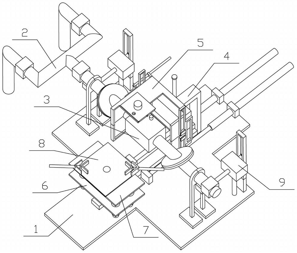
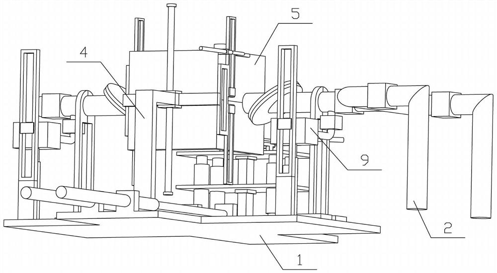
[0032] Combine below Figure 1-11 Describe this embodiment, the present invention relates to the technical field of self-priming pumps, more specifically self-priming pumps, including a chassis 1, a conveying device 2, a self-priming pump 3, a lifting device 4, a cooling device 5, a lifting device 6, and a rotating device 7 , clamping device 8 and liquid storage device 9, the present invention is convenient to change the input and output direction of the self-priming pump.

[0033]The bottom frame 1 is fixedly connected with a conveying device 2, the conveying device 2 communicates with the self-priming pump 3, the lifting device 4 is slidably connected with the bottom frame 1, the cooling device 5 is slidably connected with the lifting device 4, and the cooling device 5 is connected with the conveying device 2 Cooperate, the lifting device 6 is slidably connected on the chassis 1, the lifting device 6 is fixedly connected with the lifting device 4, the rotating device 7 is fi...

specific Embodiment approach 2

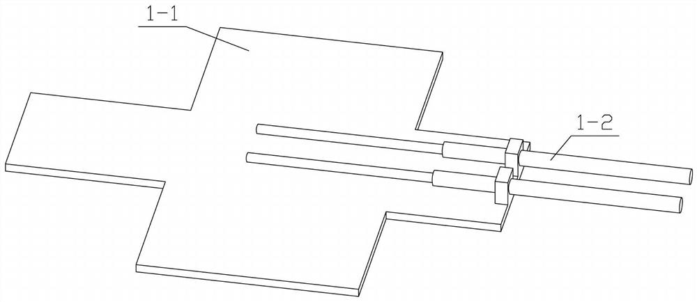
[0035] Combine below Figure 1-11 Describe this embodiment, this embodiment will further explain the first embodiment, the chassis 1 includes a bottom plate 1-1 and an electric push rod I1-2, and two electric push rods I1-2 are fixedly connected to the bottom plate 1-1 ; By starting the telescopic movement of the electric push rod I1-2, the lifting device 4 and the lifting device 6 can be moved along the front and rear directions, and then the cooling device 5 and the clamping device 8 can be driven to move along the front and rear directions.

specific Embodiment approach 3

[0037] Combine below Figure 1-11 Describe this embodiment, this embodiment will further explain the second embodiment, the delivery device 2 includes a branch pipe 2-1, a main pipe 2-2, a bracket 2-3, an on-off valve I2-4 and an on-off valve II2-5, There are two branch pipes 2-1, the two branch pipes 2-1 and the main pipe 2-2 are connected by a tee, the support 2-3 is composed of two and a half supports, and the support 2-3 is provided with two, two supports The lower part of 2-3 is fixedly connected with the bottom plate 1-1, the two brackets 2-3 are installed on the main pipe 2-2, the two branch pipes 2-1 are equipped with on-off valve I2-4, the main pipe 2-2 On-off valve II 2-5 is installed at the left and right ends, two sets of flanges are set on the main pipe 2-2, each set of flanges are fixed by studs; on-off valve I 2-4 has a control valve 2-1 for liquid circulation or cut-off function, the on-off valve II 2-5 plays the function of facilitating the disassembly and as...


PUM


Abstract

The invention relates to the technical field of self-priming pumps, in particular to a self-priming pump which comprises a bottom frame, a conveying device, a self-priming pump body, a lifting device,a cooling device, an elevating device, a rotating device, a clamping device and liquid storage devices. The conveying device is fixedly connected onto the bottom frame and communicates with the self-priming pump body; the lifting device is slidably connected with the bottom frame; the cooling device is connected with the lifting device in a sliding mode; the cooling device is matched with the conveying device; the elevating device is connected onto the bottom frame in a sliding mode; the elevating device is fixedly connected with the lifting device; the rotating device is fixedly connected onto the elevating device, and is fixedly connected with the clamping device; the self-priming pump can be clamped through the clamping device; the number of the liquid storage devices is two; the two liquid storage devices are both connected with the conveying device through pipelines; and the two liquid storage devices are both fixedly connected with the bottom frame. According to the self-primingpump provided by the invention, the input and output directions of the self-priming pump can be conveniently changed.

Description

technical field [0001] The invention relates to the technical field of self-priming pumps, more specifically self-priming pumps. Background technique [0002] Now there is a patent number: CN201621243501.3 A liquid ring vacuum-assisted non-clogging high-suction self-priming pump, including a self-priming pump body, a self-priming pump motor, a water ring vacuum pump, and a self-priming pump outlet check valve , vacuum pump exhaust pipe, vacuum pump circulating water tank, vacuum pump automatic control box, self-priming pump water outlet, self-priming pump water inlet a, self-priming pump water inlet b, self-priming pump detachable cleaning cover, fixed bottom plate and Vacuum pump motor; the utility model provides a liquid-ring vacuum-assisted non-clogging high-suction self-priming pump with a novel structure; it avoids the use of a rotary vane vacuum pump due to the disadvantage of poor steam-water separation, which causes the vacuum pump to suck liquid and be damaged Vacu...

Claims


Application Information

Patent Timeline
IPC IPC(8): F04D9/02F04D15/00F04D29/00
CPCF04D9/02F04D15/00F04D15/0005F04D29/007
Inventor 袁建梅
Owner 袁建梅
Why Eureka
Try Eureka