PWM dimming circuit used for high-power-factor primary-side-feedback LED driving power supply

A LED drive, high power factor technology, applied in the field of PWM dimming circuit, can solve the problems of poor dimming linearity, increase the operating frequency of LED drive power supply, limited range, etc., to achieve improved dimming linearity, superior PWM dimming light effect effect

Active Publication Date: 2017-07-14
深圳天源中芯半导体有限公司
View PDF8 Cites 5 Cited by
  • Summary
  • Abstract
  • Description
  • Claims
  • Application Information

AI Technical Summary

Problems solved by technology

[0006] The traditional PWM dimming circuit used for high power factor primary side feedback LED driving power has the following disadvantages: the traditional PWM dimming circuit increases the duty cycle of the LED driving power with the decrease of the duty cycle of the PWM signal during the dimming process. working frequency
As a result, PWM dimming has poor dimming linearity at low duty ratios, thus limiting the range of PWM dimming duty ratios
[0007] In the design of high power factor primary side feedback LED drive power supply that pays attention to cost and pursues high-quality PWM dimming performance, this traditional PWM dimming control circuit has more and more limitations.

Method used


Image

  • PWM dimming circuit used for high-power-factor primary-side-feedback LED driving power supply
  • PWM dimming circuit used for high-power-factor primary-side-feedback LED driving power supply
  • PWM dimming circuit used for high-power-factor primary-side-feedback LED driving power supply

Examples


Embodiment Construction

[0020] Specific embodiments of the present invention will be further described in detail below in conjunction with the accompanying drawings.

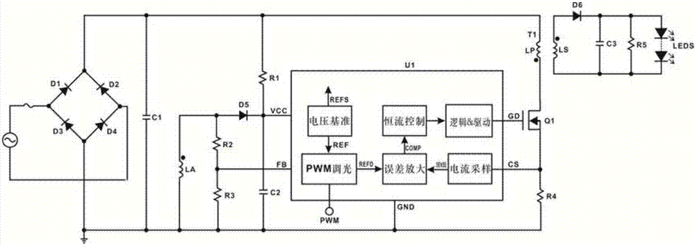
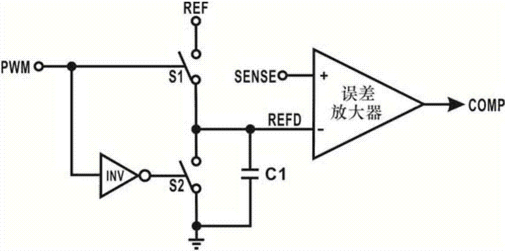
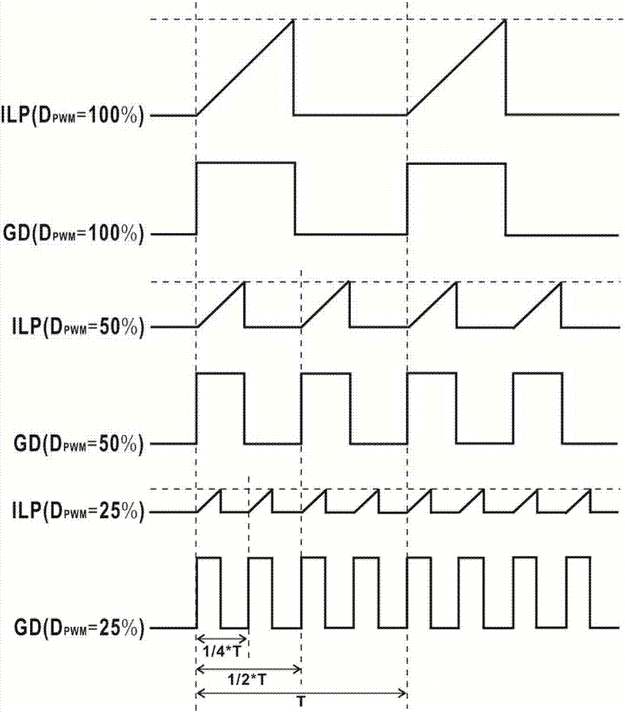
[0021]The invention solves the problem that the operating frequency of the LED drive power continuously increases with the decrease of the PWM dimming duty cycle in the traditional PWM dimming control technology used for high power factor primary side feedback LED drive power, and also solves the problem that The traditional PWM dimming control technology solves the problem that the output current dimming linearity effect is not ideal when the PWM signal is a low duty cycle, and provides a PWM dimming control circuit that solves the above problems. By reducing the reference voltage of the output current and increasing the idle time of the secondary winding of the transformer, the operating frequency of the LED drive power supply is controlled within an appropriate range, and at the same time the peak current of the primary winding of th...


PUM


Abstract

The invention discloses a PWM dimming control circuit used for a high-power-factor primary-side-feedback LED driving power supply. The PWM dimming control circuit comprises a voltage reference generation unit, a PWM processing unit, a current sampling unit, an error amplification unit, a constant current control unit, a zero-crossing detection unit, a transformer secondary winding idle time control unit and a logical and driving unit, wherein the transformer secondary winding idle time control unit is used for controlling the duration of the transformer secondary winding idle time in PWM dimming to output a signal for controlling conduction of a power switch tube; and the logical and driving unit is used for performing logical control on the constant current control unit and the output signal of the transformer secondary winding idle time control unit, so as to further drive the power switch tube and control the transformer secondary winding idle time control unit.

Description

technical field [0001] The invention relates to a PWM dimming circuit, in particular to a PWM dimming circuit used for a high power factor primary side feedback LED driving power supply. Background technique [0002] With the development of LED driving power and the requirements of green energy saving and environmental protection, LED driving power generally has a dimming function at present. Among various dimming methods, PWM dimming is the most common and abundant one. The PWM dimming circuit of the LED drive power supply uses the PWM signal output by the external MCU to control the output current of the LED drive power supply, thereby adjusting the brightness of the LED to achieve the purpose of PWM dimming. [0003] For the high power factor primary side feedback LED drive power supply, in terms of PWM signal control of the output current of the LED drive power supply, the traditional solution is to convert the PWM signal output by the external MCU into a corresponding ...

Claims


Application Information

Patent Timeline
Patent Type & Authority Applications(China)
IPC IPC(8): H05B33/08H05B44/00
CPCH05B45/10Y02B20/30
Inventor 邓小兵
Owner 深圳天源中芯半导体有限公司
Why Eureka
Try Eureka