
Mold used for engine driving motor

An engine-driven, mold-based technology, applied in the direction of manufacturing tools, casting molding equipment, casting molds, etc., can solve the problems of difficult gas discharge in grooves, pores, and air trapping, so as to prevent the cold material from being too fast, facilitate force, and The effect of easy splitting

Pending Publication Date: 2017-07-18
响水县融升科技有限公司
View PDF7 Cites 0 Cited by
  • Summary
  • Abstract
  • Description
  • Claims
  • Application Information

AI Technical Summary

Problems solved by technology

[0003] However, due to the large casting components of traditional molds, gas trapping occurs during the filling process, resulting in air holes after product processing. The air hole is set at the bottom of the mold, making it difficult to discharge the gas in some grooves
Another disadvantage of traditional casting molds is that the size of the joints of the molds is the same, and the outside of the mold is relatively smooth, which makes it more laborious to remove the mold

Method used


Image

  • Mold used for engine driving motor
  • Mold used for engine driving motor

Examples


Embodiment Construction

[0018] The following will clearly and completely describe the technical solutions in the embodiments of the present invention with reference to the accompanying drawings in the embodiments of the present invention. Obviously, the described embodiments are only some, not all, embodiments of the present invention. Based on the embodiments of the present invention, all other embodiments obtained by persons of ordinary skill in the art without making creative efforts belong to the protection scope of the present invention.

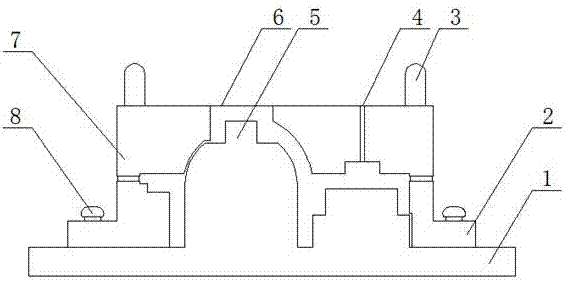
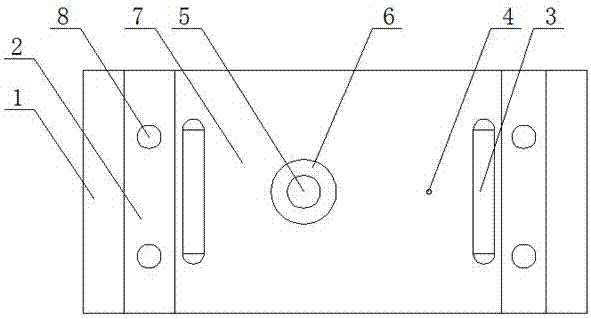
[0019] see Figure 1-2 , the present invention provides a technical solution: a mold for an engine-driven motor, including a mold core base 1, a mold cover base 2, a mold core 5 and a mold cover 7, and a mold core is fixedly connected to the upper part of the mold core base 1 5. The upper part of the mold core base 1 is movably installed with a mold sleeve base 2, and both sides of the mold sleeve base 2 are screwed with fixing bolts 8, and the mold sleeve bas...


PUM


Abstract

The invention discloses a mold used for an engine driving motor. The mold comprises a mold core base, a mold sleeve base, a mold core and a mold sleeve. The mold core is fixedly connected to the upper portion of the mold core base. The mold sleeve base is movably installed on the upper portion of the mold core base. The two sides of the mold sleeve base are both in threaded connection with fixing bolts. The mold sleeve base is movably connected with the mold core base through the fixing bolts. The mold sleeve is fixedly connected to the upper portion of the mold sleeve base. Exhaust holes are uniformly formed in the outside of the mold sleeve. A pouring gate is fixedly arranged at the center of the top of the mold sleeve. According to the mold used for the engine driving motor, the ends, located in the mold sleeve, of the exhaust holes are all arranged in the deepest position of a groove in the mold sleeve, and the situation that pores occur after a product is machined is prevented; and the length of the mold core base is larger than that of the mold sleeve base, the mold core base with the larger length is trodden on with both feet, and a user can conveniently separate the casted mold.

Description

technical field [0001] The invention relates to the technical field of mold manufacturing for a drive motor, in particular to a mold for an engine drive motor. Background technique [0002] Casting mold means that in order to obtain the structural shape of the part, other easy-to-form materials are used to make the structural shape of the part in advance, and then the mold is placed in the sand mold, so a cavity with the same structural size as the part is formed in the sand mold. Then pour a fluid liquid into the cavity, and after the liquid cools and solidifies, it can form a part exactly the same as the shape and structure of the mold. [0003] However, due to the large casting components of traditional molds, air trapping occurs during the filling process, resulting in air holes after product processing. Air holes are set at the bottom of the mold, making it difficult for the gas in some grooves to escape. Another disadvantage of traditional casting molds is that the j...

Claims


Application Information

Patent Timeline
IPC IPC(8): B22C9/02B22C9/24
CPCB22C9/02B22C9/24
Inventor 王兴余
Owner 响水县融升科技有限公司
Learn More