Worm type lifting mechanism and system

A lifting mechanism, worm-type technology, applied in the direction of lifting devices, mechanical equipment, gear transmission devices, etc., can solve the problems of low lifting efficiency of electric lifting devices, time-consuming and labor-consuming lifting devices, high motor torque requirements, etc., to achieve fast locking and unlocking process Reliable, avoid safety hazards, safe and fast operation

Active Publication Date: 2017-07-18
SICHUAN JOINER MACHINERY & AUTOMATIC EQUIP
View PDF5 Cites 4 Cited by
  • Summary
  • Abstract
  • Description
  • Claims
  • Application Information

AI Technical Summary

Problems solved by technology

[0007] The purpose of the present invention is to overcome that in the existing shelter lifting device, the purely manual lifting device is time-consuming and laborious and has safety risks, while the electric lifting device has low lifting efficiency and high requirements on motor torque, and when the shelter has a large self-weight , the shelter has the technical problem of momentum swinging or unsteady conditions, and a worm-type lifting mechanism and system are provided. The lifting mechanism provides a large rotational torque through the conversion of the worm gear reducer and reduces the torque requirement of the driving device, and Utilizing the self-locking performance of the worm gear and worm, the cabin can be lifted and lowered smoothly, and the operation is safe and fast, which is suitable for the needs of rapid field rescue and other operations.

Method used


Image

  • Worm type lifting mechanism and system
  • Worm type lifting mechanism and system
  • Worm type lifting mechanism and system

Examples


Embodiment 1

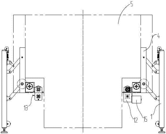
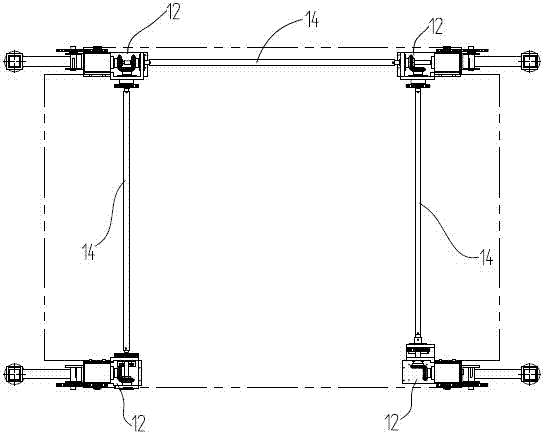
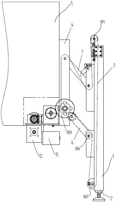
[0050] Such as Figure 1 to Figure 4 As shown, the worm-type lifting mechanism of this embodiment includes a grounding leg supported on the ground and a shelter support 4 connected to the shelter 5. The grounding leg includes an outer sleeve 1 and is arranged between the outer sleeve 1. The inner casing 2 in the inner casing also includes a transmission chain 3 connected to the shelter support 4 and the outer casing 1 respectively, and the transmission chain 3 is equipped with a driving wheel 303 connected with the driving device, and the transmission chain 3 passes through When the driving device is driven and running, the outer casing 1 and the shelter support 4 rise and fall synchronously; as a special design of the present invention, a worm gear reducer 12 is connected between the driving wheel 303 and the driving device. In this embodiment, the driving The device is a motor 15, and when the motor 15 drives the drive wheel 303 to rotate, the shelter support 4 lifts under t...

Embodiment 2

[0057] Such as Figure 5 to Figure 9 As shown, the worm-type elevating mechanism described in Embodiment 1 is provided with a forced opening and closing device on the upper connecting rod 7, including a deadbolt rod 9 cooperating with the locking hole 701 on the upper connecting rod 7. The middle part between the two ends of the deadbolt rod 9 is hinged on the pole connecting plate 17 on the outer sleeve 1, and the dead bolt hole 901 is correspondingly arranged in the middle part of the deadbolt rod 9, one end of the deadbolt rod 9 is a dead bolt, and the other end is hinged There is a transmission part, and the free end of the transmission part is hinged with a limiting part arranged at the lower end of the outer sleeve 1 , and the limiting part is hinged with the outer sleeve 1 .

[0058] Further, the transmission part is a long connecting rod 8 with a rod-shaped structure, which is arranged outside the grounding leg. The transmission part is set as a long connecting rod to...

Embodiment 3

[0064] Such as Figure 5 to Figure 9As shown, according to the worm-type lifting mechanism described in Embodiment 1, the limiting plate 10 and the inner sleeve 2 are also provided with a positioning structure correspondingly, and the positioning structure includes a positioning member arranged on the inner sleeve 2, And the positioning groove 1003 correspondingly provided on the limiting plate 10 , when the positioning piece is retracted into the outer sleeve 1 along with the inner sleeve 2 , the positioning piece is combined with the positioning groove 1003 . The positioning structure set by the limiting plate and the inner sleeve, when the shelter is lowered to the limit position, through the cooperation of the positioning piece and the positioning groove, the inner sleeve is restricted from continuously upward, which plays a role in safely protecting the entire lifting mechanism.

[0065] Such as Image 6 As shown, the limiting plate 10 is provided with a limiting shaft h...


PUM


Abstract

The invention discloses a square cabin lifting device and relates to a worm type lifting mechanism. The worm type lifting mechanism comprises a drive wheel and a drive device which are arranged in cooperation with a transmission chain. A worm gear reducer is assembled between the drive wheel and the drive device. When the drive device drives the drive wheel to rotate, a square bin support ascends and descends under the drive of the transmission chain. A worm type lifting system comprises four worm type lifting mechanisms arranged at the four corners of a square bin in a supported manner. The lifting mechanism provides large rotation torque for conversion of the worm gear reducer and lower the requirement for torque of the drive device; in addition, the square cabin can ascend and descend stably and is safely and rapidly operated due to the self-locking performance of a worm wheel and a worm, and the use requirement for actions such as fast field emergency rescue is met; and in addition, transmission rods are sequentially connected with the lifting system composed of the worm type lifting mechanisms, synchronous ascending and descending of four supporting points of the square cabin are ensured, one person is enough for one-point operation, labor force is saved, and the lifting efficiency is improved.

Description

technical field [0001] The invention relates to a shelter lifting device, in particular to a worm-type lifting mechanism and system. Background technique [0002] The structure of the shelter is similar to that of a container, usually welded by metal sheets, and the shelter is usually equipped with a vehicle, usually a pickup truck, which is transported to the required place by the vehicle, and its standard is also formulated with reference to the container standard. Compared with the container, the shelter has higher maneuverability. Using the space of the shelter to configure various items and equipment can provide reliable guarantee for field rescue and other operations. As the shelter is used in emergency rescue, fire fighting, communication, military Widely used in fields such as mobile phones and other fields, the lifting of the shelter is very important in the process of use and transfer. [0003] The weight of the shelter equipped with equipment and objects is relat...

Claims


Application Information

Patent Timeline
Patent Type & Authority Applications(China)
IPC IPC(8): B66F11/00B66F13/00F16H1/16
CPCB66F11/00B66F13/00F16H1/16
Inventor 余应林
Owner SICHUAN JOINER MACHINERY & AUTOMATIC EQUIP
Why Eureka
Try Eureka