Supercharge Your Innovation With Domain-Expert AI Agents!

Control circuit of LED driving power

A LED drive and control circuit technology, applied in the field of control circuits, can solve the problems of uncontrolled power supply and achieve the effects of low cost, improved reliability and novel design

Inactive Publication Date: 2017-07-18
李少华
View PDF0 Cites 0 Cited by
  • Summary
  • Abstract
  • Description
  • Claims
  • Application Information

AI Technical Summary

Problems solved by technology

[0002] The existing LED driver integrated circuit power supply is stepped down by a resistor, filtered by a capacitor and directly connected to the power supply pin of the LED driver integrated circuit, so that the power supply is not controlled

Method used


Image

  • Control circuit of LED driving power

Examples


Embodiment Construction

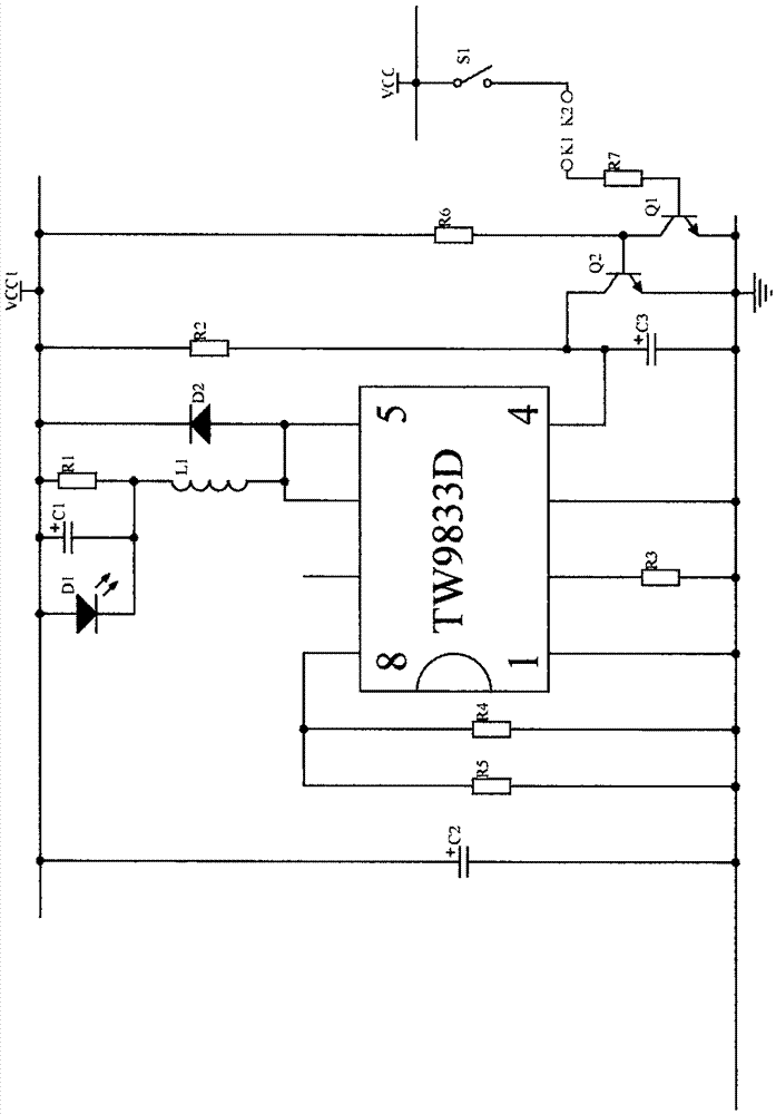
[0009] figure 1 In the control circuit of the LED drive power supply, there are two power supplies VCC and VCC1, light-emitting diode D1, diode D2, capacitors C1, C2, C3, inductor L1, resistors R1, R2, R3, R4, R5, and LED drive integrated circuits. LED drive circuit, one end of the switch S1 is connected to the positive power supply VCC, the other end is connected to the switch signal output pin K2, the collector of the triode Q2 is connected to the power pin of the LED driver integrated circuit, the emitter of Q2 is grounded, the base of Q2 is connected to the collector of the triode Q1, and the emitter of Q1 Grounded, the resistor R6 is connected to the positive power supply VCC1 and the collector of Q1 respectively, and the series resistor R7 to the base of Q1 is connected to the signal input pin K1.

[0010] Its working process is as follows: When the LED driver is working, K1 is connected to K2. S1 is closed, Q1 is turned on, Q2 is turned off, there is voltage on the pow...


PUM


Abstract

The invention provides a control circuit of an LED driving power. The control circuit of an LED driving power is characterized in that two triodes are used to perform phase inversion control on the voltage of a power pin of an LED driving integrated circuit, so that the power supply of the LED driving integrated circuit is controlled and then on / off of an LED lamp can be controlled.

Description

technical field [0001] The invention relates to a control circuit of an LED driving integrated circuit power supply, in particular to a control circuit of the LED driving power supply. Background technique [0002] The existing LED driving integrated circuit power supply uses a resistor to drop the voltage, and uses a capacitor to filter and directly connect to the LED driving integrated circuit power supply pin, so that the power supply is not controlled. Contents of the invention [0003] The purpose of the present invention is to overcome the deficiencies in the prior art and provide a control circuit for LED drive power supply. In this circuit, two triodes are used to invert the phase to control the voltage of the power supply pin of the LED drive integrated circuit, so that the LED drive integrated circuit The power supply of the circuit is controlled, thereby controlling the on and off of the LED light. [0004] The technical solution of the present invention is: th...

Claims


Application Information

Patent Timeline
Patent Type & Authority Applications(China)
IPC IPC(8): H05B33/08H05B44/00
CPCH05B45/40
Inventor 李少华
Owner 李少华
Features
  • R&D
  • Intellectual Property
  • Life Sciences
  • Materials
  • Tech Scout
  • Unparalleled Data Quality
  • Higher Quality Content
  • 60% Fewer Hallucinations
Learn More