
Grain air-drying harrow

A grain and tooth harrow technology, applied in the field of agricultural implements, can solve the problems of high labor intensity and low efficiency of tumbling, and achieve the effect of overcoming high labor intensity and low efficiency of tumbling

Inactive Publication Date: 2017-07-21
曹锦钰
View PDF0 Cites 0 Cited by
  • Summary
  • Abstract
  • Description
  • Claims
  • Application Information

AI Technical Summary

Problems solved by technology

[0002] Data query shows that the total grain output of the country last year exceeded 600 million tons, and the amount of grain that farmers need to dry is huge. However, at present, manual drying is carried out with wooden lifts. This method is labor-intensive and low-efficiency.

Method used


Image

  • Grain air-drying harrow

Examples


Embodiment Construction

[0015] The present invention will be further explained below in conjunction with the accompanying drawings and embodiments.

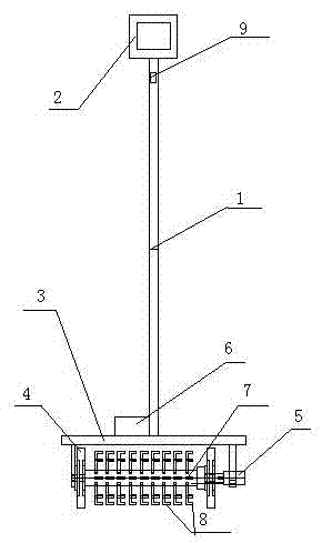
[0016] Such as figure 1 As shown, a grain drying rake includes a pole 1, a handle 2 disposed at one end of the pole 1, a positioning frame 3 disposed at the other end of the pole 1, a moving device 4 disposed on the positioning frame 3, and a rake device , a motor 5 located on one side of the rake device, a mobile power supply 6 compatible with the motor 5, the rake device includes a connecting shaft 7 and several rake nails 8 evenly arranged on the outer periphery of the connecting shaft 7, the connecting shaft 7 Compatible with the rotating shaft of the motor 5, the pole 1 or the handle 2 is provided with a control button 9, and the control button 9, the mobile power supply 6 and the connecting shaft 7 are connected by electric wires to form a circuit loop.

[0017] Mobile power supply 6 is a battery or storage battery device. The pole 1 is a telesc...


PUM


Abstract

The invention discloses a grain drying rake, which comprises a support rod (1), a handle (2) provided at one end of the support rod (1), a positioning frame (3) provided at the other end of the support rod (1), a The mobile device (4) and the rake device on the frame (3), the motor (5) arranged on one side of the rake device, and the mobile power supply (6) matched with the motor (5), the rake device includes The connecting shaft (7) and several rake nails (8) uniformly arranged on the outer periphery of the connecting shaft (7), the connecting shaft (7) is adapted to the rotating shaft of the motor (5). The invention has the advantages of saving time and labor, and solves the problem of low tumbling efficiency while overcoming the high labor intensity caused by manual tumbling.

Description

technical field [0001] The invention relates to agricultural implements, in particular to a grain drying rake. Background technique [0002] Data query shows that the total national grain output last year exceeded 600 million tons, and the amount of grain that farmers need to dry is huge. However, at present, manual drying is carried out with wooden lifts. This method is labor-intensive and low-efficiency. Contents of the invention [0003] The purpose of the invention is to overcome the problems of the prior art and provide a grain drying rake. [0004] A grain drying rake of the present invention comprises a pole, a handle disposed on one end of the pole, a positioning frame disposed on the other end of the pole, a moving device disposed on the positioning frame and a rake device, and a rake device disposed on the rake device. The motor on the side, the mobile power supply matching the motor, the rake device includes a connecting shaft and a number of rake nails uniform...

Claims


Application Information

Patent Timeline
IPC IPC(8): A23B9/08A01F25/00
CPCA23B9/08A01F25/00
Inventor 曹锦钰
Owner 曹锦钰
Learn More