Water-saving and gas-venting closestool

A toilet and exhaust cap technology, applied in the field of "water-saving exhaust toilet, can solve the problems of wasting water resources, poor deodorization effect, etc., and achieve the effect of saving water, simple and easy manufacturing process, and maintaining air

Inactive Publication Date: 2017-07-21
赵桂平
View PDF0 Cites 1 Cited by
  • Summary
  • Abstract
  • Description
  • Claims
  • Application Information

AI Technical Summary

Problems solved by technology

[0004] In order to solve the problems of waste of water resources and poor deodorizing effect of existing toilets, the present invention provides a water-saving exhaust toilet. During the process, or when it is idle, it has been exhausting from the water outlet in the toilet to the outside through the overflow pipe exhaust pipe to make the indoor air fresh
[0005] In order to solve the problems of waste of water resources and poor deodorizing effect of the existing toilet, the technical solution adopted by the present invention is: only the water outlet of the toilet has a built-in water outlet pipe, and the toilet bends obliquely downward from the concave point at the bottom A section of sewage pipe mouth, a section of smooth inner wall, durable rubber hose with good extension and elasticity is sleeved on the nozzle. Several arc-shaped rubber corrugations are set on the upper half of the hose, and the rear end of the hose is sleeved on the elbow positioned by a tripod. There is a groove-shaped slide plate support, the lower end of the elbow is sleeved with the sewage pipe and introduced into the sewage pit mouth, and an outer sleeve that can be fastened at both ends is provided.

Method used


Image

  • Water-saving and gas-venting closestool
  • Water-saving and gas-venting closestool
  • Water-saving and gas-venting closestool

Examples


Embodiment Construction

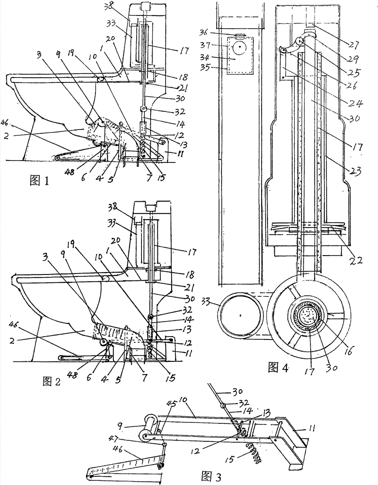
[0026] In Figure 1 and Figure 2, only the water outlet of the toilet is equipped with an internal water outlet pipe 1, and a section of sewage discharge pipe 2 is bent directly backward and downward from the concave point at the bottom of the toilet, and a section of inner wall is sleeved on the pipe mouth. The durable rubber hose 3 has several arc-shaped rubber corrugations on the upper half of the hose. The rear end of the hose is sleeved on the elbow 5 positioned by the tripod 4. There is a groove-shaped slide plate support 6 under the hose. The lower end of the elbow is connected to the sewage pipe to guide the sewage In the mouth of the pit, there is a section of outer casing 7 that can be fastened at both ends. The lower end is set on the mouth of the sewage pit 8 to close, and the upper end is closed with the outer periphery of the sewage pipe. In Fig. 1, Fig. 2, and Fig. 3, a The shaft roller 9 for lifting the rubber hose, and the two frames at the rear end of the posit...


PUM


Abstract

A water-saving exhaust toilet, the toilet is directly bent from the bottom of the toilet to a section of sewage discharge nozzle, and a section of flexible rubber hose is sleeved on the nozzle, and the rear end of the rubber hose is connected with a positioning elbow and a sewage discharge pipe. The improved Drain valve, make the pull rod under the button press lever link to the shaft roller to lower the hose gate, the dirt will be discharged by itself, and the flushing water will flush the inner wall of the toilet and the bottom of the toilet in a super-rotating way. When the shaft roller lifts the hose, the hose becomes the gate of the sewage outlet , Block the remaining water and seal the aftertaste. Connect the improved overflow pipe to the exhaust pipe. At the appropriate section of the pipe, install a jacket box with a small exhaust fan. The pipe is connected to the exhaust cap of the tail fin, which is located in the windy place outdoors, so that it can exhaust itself all the time. Use a small exhaust fan to deodorize. When the outdoor wind force is greater than level 3, the exhaust cap will automatically deodorize the toilet and keep the indoor air fresh. The toilet has no auxiliary flushing nozzle, saves the water for auxiliary flushing, and saves about half of the water compared with the general siphon toilet, which is of great significance to my country where water resources are scarce.

Description

[0001] Technical field [0002] The invention belongs to facilities in the bathroom, and is a toilet, in particular a "water-saving exhaust toilet" with water-saving and exhaust functions. Background technique [0003] At present, most of the known toilets use the siphon sewage discharge method, which requires a large amount of water to flush through the high point of the built-in pipeline to produce a siphon, which not only wastes water, but also easily clogs the toilet. Most of the known smart flush toilets use deodorant or adsorption The deodorization method does not discharge the odorous substances, and the effect is not good. Contents of the invention [0004] In order to solve the problems of waste of water resources and poor deodorizing effect of existing toilets, the present invention provides a water-saving exhaust toilet. During the process, or when idle, the water outlet in the toilet is exhausted to the outside through the overflow pipe exhaust pipe, so that the...

Claims


Application Information

Patent Timeline
Patent Type & Authority Applications(China)
IPC IPC(8): E03D11/16E03D1/34E03D9/05
CPCE03D11/16E03D1/34E03D9/05
Inventor 赵桂平
Owner 赵桂平
Why Eureka
Try Eureka