A gearbox shaft locking structure

A technology of locking structure and gearbox, applied in the field of gearbox, can solve the problems of complex structure, large space for parking gear, etc., and achieve the effect of simple structure

Active Publication Date: 2018-11-16
ANHUI JIANGHUAI AUTOMOBILE GRP CORP LTD
View PDF5 Cites 0 Cited by
  • Summary
  • Abstract
  • Description
  • Claims
  • Application Information

AI Technical Summary

Problems solved by technology

[0004] The purpose of the present invention is to provide a gearbox shaft locking structure to solve the problem that the installation plane of the parking gear needs a large space and the structure is complicated

Method used


Image

  • A gearbox shaft locking structure
  • A gearbox shaft locking structure
  • A gearbox shaft locking structure

Examples


Embodiment Construction

[0030] The technical solution of the present invention is described in detail below through the examples, and the following examples are only exemplary and can only be used to explain and illustrate the technical solution of the present invention, rather than being interpreted as a limitation to the technical solution of the present invention.

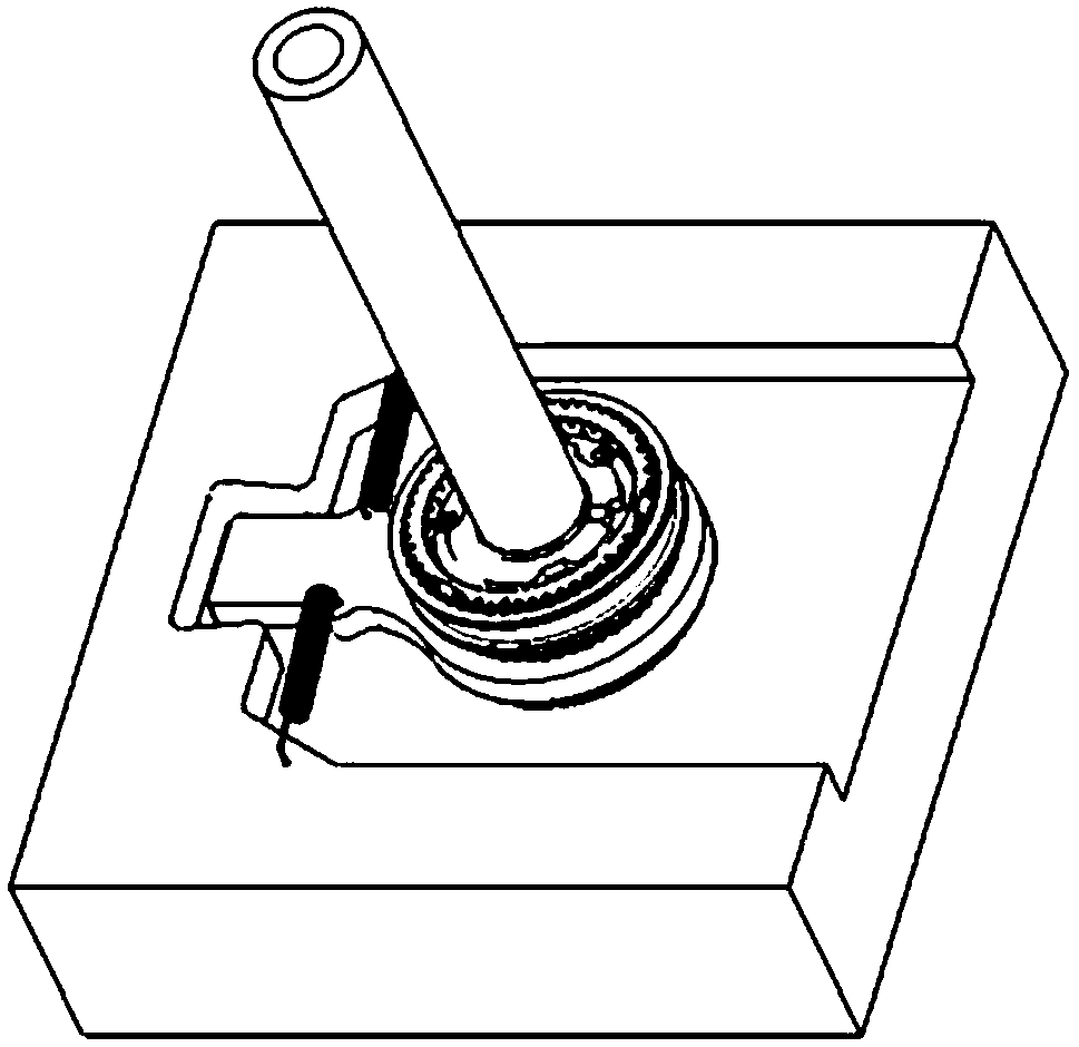
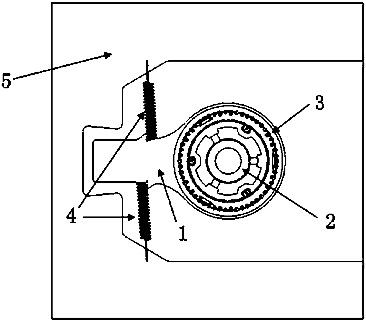
[0031] This application uses synchronous shifting combined with teeth to realize the selection of the locking gear. The locking wheel is a swing arm structure, and the mechanical locking within a small angle can be realized by means of the structure of the gearbox housing. , The locking wheel is relatively static or returned by the return spring.

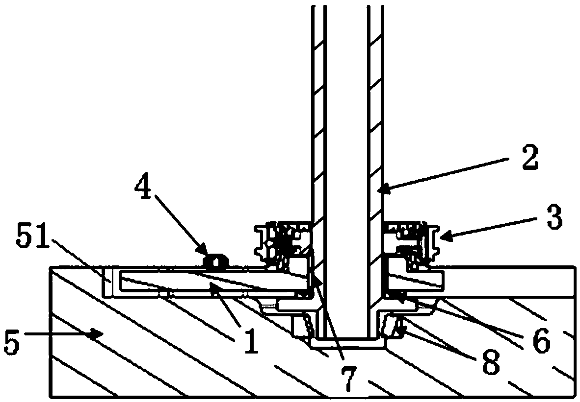
[0032] Such as figure 1 with figure 2 As shown, the gearbox shaft locking structure of the present application includes a gearbox case 5, a locking wheel 1, a gear shaft 2, a synchronizer assembly 3, and two return springs 4, wherein the gearbox case is the entire transmission Part of the...


PUM


Abstract

The invention relates to a shafting locking structure of a transmission. The shafting locking structure of the transmission comprises a transmission case, a locking gear, a gear shaft, a synchronizer assembly, reset springs, a thrust bearing, a needle bearing and a cone bearing, wherein the surface, opposite to the locking gear, of the transmission case is provided with a limiting groove; the locking gear is arranged in the limiting groove; the locking gear is in rotation connection with the end part of the gear shaft through the needle bearing and the thrust bearing; the lower end of the gear shaft is in rotation connection with the transmission case through the cone bearing; the synchronizer assembly is arranged on the gear shaft; and the synchronizer assembly is movably meshed with the locking gear. According to the technical scheme of the invention, through cooperation of the locking gear, the limiting groove and the synchronizer assembly, mechanical locking of a shafting is realized at a smaller rotation angle; selection of locking gear stages is realized on the condition that the arrangement of the shafting is basically unchanged; and the structure is simple.

Description

technical field [0001] The invention belongs to the technical field of gearboxes, in particular to a gearbox shaft locking structure. Background technique [0002] Most of the existing gearbox shaft locking structures are ratchet pawls that are screwed into the plane radially, and the locking function is realized in the plane structure. [0003] Taking the parking system as an example, under the existing operation mode, after the vehicle is stopped, the driver puts the vehicle gear into the P position, and then the P position indicator lights up, indicating that the parking is successful, and then the manual / electric parking system is supplemented. car, so that the vehicle can be parked, but in this case, the parking pawl may not actually be parked in the ratchet slot, but only the push rod of the parking system has a spatial displacement, forming a thrust on the parking pawl. The pawl can be parked and finally locked after the parking gear rotates a certain angle. This ty...

Claims


Application Information

Patent Timeline
Patent Type & Authority Patents(China)
IPC IPC(8): F16H61/22F16H57/02F16H57/021
CPCF16H57/02F16H57/021F16H61/22F16H2057/02026
Inventor 王文浩张道谱
Owner ANHUI JIANGHUAI AUTOMOBILE GRP CORP LTD
Why Eureka
Try Eureka