Eureka AIR delivers breakthrough ideas for toughest innovation challenges, trusted by R&D personnel around the world.

Three-position disconnecting switch for locomotive and use method thereof

An isolating switch and three-position technology, which is applied in the direction of electric switches, air switch parts, power devices inside the switch, etc., can solve the problems that cannot be completely eliminated, such as misoperation and poor safety, so as to facilitate maintenance and ensure the safety of power supply Effect

Pending Publication Date: 2021-10-22
德华瑞尔(西安)电气有限公司
View PDF0 Cites 0 Cited by
  • Summary
  • Abstract
  • Description
  • Claims
  • Application Information

AI Technical Summary

Problems solved by technology

The conventional logical control relationship is to use the auxiliary contacts of the contactors in the control circuits of high-voltage electrical appliances to lock each other to achieve position switching. The possibility of misoperation cannot be completely ruled out by relying on the interlocking between electrical appliances, and the safety is poor.

Method used


Image

  • Three-position disconnecting switch for locomotive and use method thereof
  • Three-position disconnecting switch for locomotive and use method thereof
  • Three-position disconnecting switch for locomotive and use method thereof

Examples


Embodiment Construction

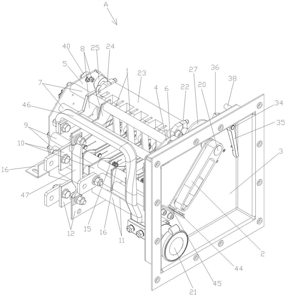
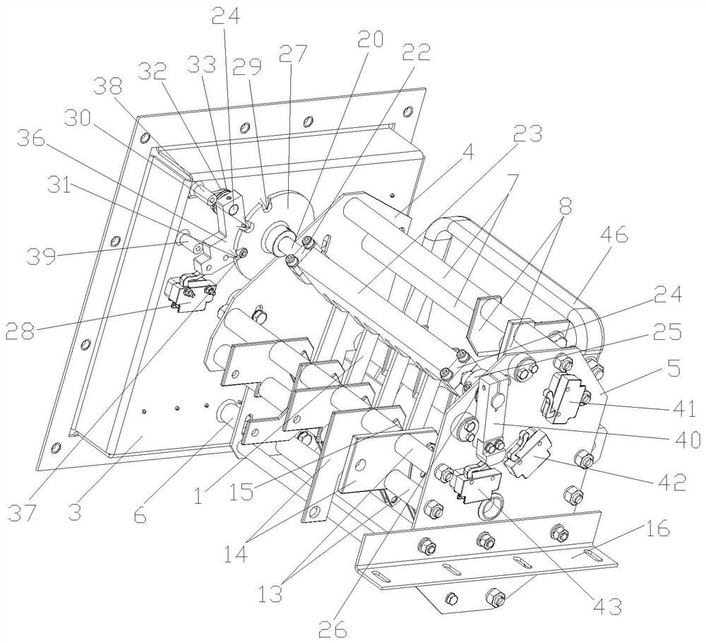
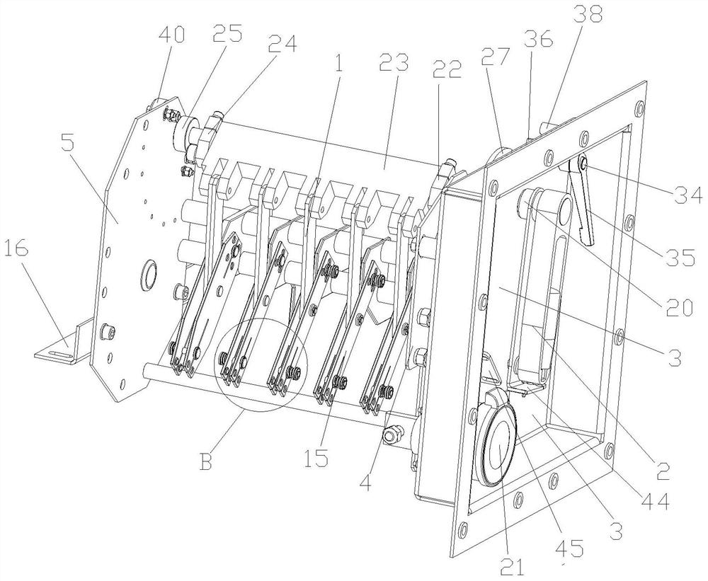
[0080] like figure 1 As shown, a three-position isolating switch for a locomotive according to the present invention includes

[0081] The first incoming line position is used to strobe the power supply line of the workshop power supply to the line position;

[0082] The second incoming line position is used to select the line that is grounded at the outgoing line position;

[0083] The third incoming line position is used to select the line that the pantograph supplies power to the line position;

[0084] The operating mechanism is used to drive the isolation knife assembly to rotate so that the outgoing wire position is connected to the first wire incoming position, the second incoming wire position or the third incoming wire position;

[0085] a detector, configured to detect the conduction signal of the first incoming line position, the second incoming line position or the third incoming line position;

[0086] The frame body is used for installing the first wire inlet ...


PUM


Abstract

The invention discloses a three-position disconnecting switch for a locomotive and a use method thereof. The switch comprises a first wire inlet position used for gating a power supply between locomotives to supply power to a wire outlet position; a second wire inlet position, used for gating a grounded circuit of the wire outlet position; a third wire inlet position, used for gating a line of the pantograph for supplying power to the wire outlet position; an operating mechanism, a detector and a frame body. The method comprises the following steps of: 1, classifying the working types of the disconnecting switches; 2, a workshop power supply supplying power to a wire outlet position; 3, grounding a wire outlet position; and 4, the pantograph supplying power to the wire outlet position. The structure is simple, the design is reasonable, the first wire inlet position and the wire outlet position, the second wire inlet position and the wire outlet position or the third wire inlet position and the wire outlet position are connected and conducted through the arrangement of the isolation knife assembly, and it is effectively avoided that the first wire inlet position, the second wire inlet position and the third wire inlet position are connected and conducted with the wire outlet position at the same time; therefore, a workshop power supply and a pantograph are prevented from supplying power to a train at the same time, mechanical locking of the disconnecting switch is effectively achieved, and power supply safety is guaranteed.

Description

technical field [0001] The invention belongs to the technical field of isolating switches, and in particular relates to a three-position isolating switch for locomotives and a method for using the same. Background technique [0002] With the rapid development of the national economy, urban rail transit has become an important means of public transportation in medium and large cities. The development of rail transit has brought a large demand for electric locomotives, and people have higher and higher requirements for equipment and personal safety. [0003] The power receiving mode of domestic rail vehicles usually has two combinations of pantograph power supply and workshop power supply. The high-voltage circuits of the two modes are not allowed to be connected to the power supply at the same time, and each high-voltage circuit needs to be locked each other, so the control requirements for the circuit are stricter , The safety of power supply puts forward higher requirements...

Claims


Application Information

Patent Timeline
IPC IPC(8): H01H31/08H01H31/02H01H3/22H01H9/16
CPCH01H31/08H01H31/02H01H3/22H01H9/16
Inventor 李嘉董晖李毅刘立华徐安博
Owner 德华瑞尔(西安)电气有限公司
Why Eureka
Eureka Blog
Learn More