Pumping-in type spiral groove dry gas seal structure with convergent type seal gap

A technology of sealing gap and dry gas seal, which is applied in the direction of engine sealing, engine components, mechanical equipment, etc., can solve the problem of high leakage rate, unsatisfactory guarantee of stability and reliability of dynamic pressure dry gas seal, and complicated structure. And other issues

Inactive Publication Date: 2017-07-21
KUNMING UNIV OF SCI & TECH
View PDF8 Cites 0 Cited by
  • Summary
  • Abstract
  • Description
  • Claims
  • Application Information

AI Technical Summary

Problems solved by technology

In ordinary centrifugal pumps, reactors and other rotating machines with low speed, the stability and reliability of the dynamic pressure dry gas seal cannot be guaranteed satisfactorily. It has a larger opening force when it stops, but compared with the dynamic pressure type dry gas seal, the static pressure type dry gas seal has disadvantages such as complicated structure, high leakage rate, and more external factors affecting its sealing performance.

Method used


Image

  • Pumping-in type spiral groove dry gas seal structure with convergent type seal gap
  • Pumping-in type spiral groove dry gas seal structure with convergent type seal gap
  • Pumping-in type spiral groove dry gas seal structure with convergent type seal gap

Examples


Embodiment 1

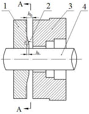
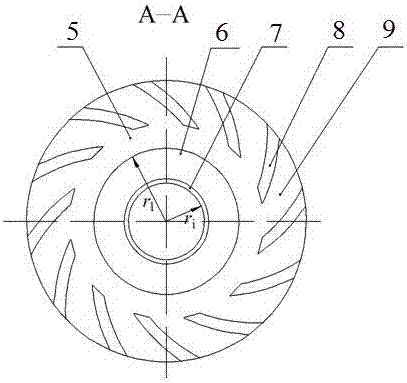
[0022] Such as figure 1 with figure 2 As shown, a pump-in type spiral groove dry gas seal structure with a convergent sealing gap includes two sealing rings, namely the moving ring 1 and the static ring 3, and there are evenly opened circumferentially on the outer diameter side of the end surface of the moving ring 1 12 spiral grooves 8, the groove depth is 3 μm, the helix angle is 15°, the gas flows radially from the outer diameter side to the inner diameter side; a transition surface 6 is processed at the position near the inner diameter of the end surface of the moving ring 1, so that the two The sealing gap between the sealing rings forms a convergent sealing gap 2 along the gas flow direction, and the transition surface 6 is in the form of a conical surface;

[0023] The distance from the beginning of the transition surface 6 to the center of the seal ring end face r 1 Inner diameter of sealing ring r i 1.01 times of ; the angle between the 6-axis projection profil...

Embodiment 2

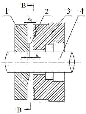
[0025] Such as image 3 with Figure 4 As shown, a pump-in spiral groove dry gas seal structure with a convergent sealing gap includes two sealing rings, namely the moving ring 1 and the static ring 3, and the outer diameter side of the end surface of the static ring 3 is evenly opened in the circumferential direction. 6 spiral grooves 8, the groove depth is 100μm, the helix angle is 5°, the gas flows radially from the outer diameter side to the inner diameter side; a transition surface 6 is processed at the position near the inner diameter of the end surface of the moving ring 1, so that the two The sealing gap between the sealing rings forms a convergent sealing gap 2 along the gas flow direction, and the transition surface 6 is in the form of a spherical surface;

[0026] The distance from the beginning of the transition surface 6 to the center of the seal ring end face r 1 Inner diameter of sealing ring r i 1.15 times of ; the angle between the transition surface 6-ax...

Embodiment 3

[0028] Such as Figure 5 with Image 6 As shown, a pump-in type spiral groove dry gas seal structure with a convergent sealing gap includes two sealing rings, namely the moving ring 1 and the static ring 3, and there are evenly opened circumferentially on the outer diameter side of the end surface of the moving ring 1 10 spiral grooves 8, the groove depth is 10μm, the helix angle is 85°, the gas flows radially from the outer diameter side to the inner diameter side; a transition surface 6 is processed at the position near the inner diameter of the end surface of the static ring 3, so that the two The sealing gap between the sealing rings forms a convergent sealing gap 2 along the gas flow direction, and the transition surface 6 is in the form of an ellipsoid;

[0029] The distance r from the beginning of the transition surface 6 to the center of the end surface of the sealing ring 1 is the inner diameter of the sealing ring r i 1.05 times of ; the angle between the transiti...


PUM

PropertyMeasurementUnit
Groove depthaaaaaaaaaa
Helix angleaaaaaaaaaa

Abstract

The invention relates to a pumping-in type spiral groove dry gas seal structure with a convergent type seal gap. The pumping-in type spiral groove dry gas seal structure comprises two seal rings, a plurality of spiral grooves are uniformly formed in the external diameter side circumferential direction of the end face of any one of the two seal rings, and gas flows from the external diameter side to the internal diameter side in the radial direction; and a transitional face is machined on the position, close to the internal diameter, of the end face of any one seal ring to enable a seal gap between the two seal rings to form the convergent type seal gap in the flowing direction of the gas. According to the pumping-in type spiral groove dry gas seal structure with the convergent type seal gap, by reasonably designing parameters of the transitional face, the hydrodynamic effect generated by the spiral grooves and the hydrostatic effect generated by the convergent seal gap are utilized, and thus the seal opening capacity is improved. Meanwhile, the seal gap is designed into a convergent type, thus the seal leakage rate can be reduced to a certain extent, and the seal property is further improved.

Description

technical field [0001] The invention relates to a pump-in type spiral groove dry gas sealing structure with a convergent sealing gap, which belongs to the technical field of mechanical sealing. Background technique [0002] The dry gas seal prevents the leakage of the sealed medium by a micron-level air film in the sealing gap. Therefore, the shape of the air film is a key factor affecting the sealing performance. Improving the end face structure of the dry gas sealing ring is a common means to improve the performance of the dry gas seal and prolong the service life of the seal. At present, the improvement of the spiral groove dry gas seal is generally reflected in the structure of the groove or the distribution of the groove, and the improvement of the end face of the sealing ring is still seldom, although some scholars have proposed to process the tapered surface on the end face of the spiral groove dry gas seal (CN 103090006B), but this case is suitable for high pressur...

Claims


Application Information

Patent Timeline
IPC IPC(8): F16J15/40
CPCF16J15/406
Inventor 宋鹏云许恒杰
Owner KUNMING UNIV OF SCI & TECH
Why Eureka
Try Eureka