Dry gas sealing structure with controllable end face rigidity
A dry gas sealing and controllable technology, applied in the direction of engine sealing, engine components, mechanical equipment, etc., can solve the problems of insufficient use effect and weak self-adaptive ability, and achieve the prevention of friction, good sealing effect, and workability. The effect of high matching
- Summary
- Abstract
- Description
- Claims
- Application Information
AI Technical Summary
Problems solved by technology
Method used
Image
Examples
Embodiment 1
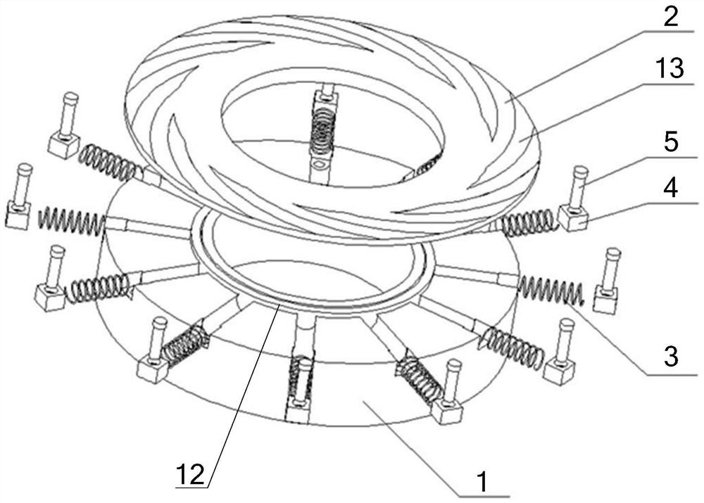
[0037] Such as figure 1 and figure 2 A dry gas seal structure with controllable end face stiffness is shown, including a moving ring and a static ring, the moving ring is a rigid end face, the static ring includes a static ring body 1, and the end face of the static ring body 1 is embedded with several The annular uniformly distributed elastic member 3 also includes an annular flat foil 2 assembled on the end surface of the static ring body 1, the flat foil 2 is in contact with the elastic member 3, and a dynamic pressure groove is opened on the surface of the flat foil 2 13.
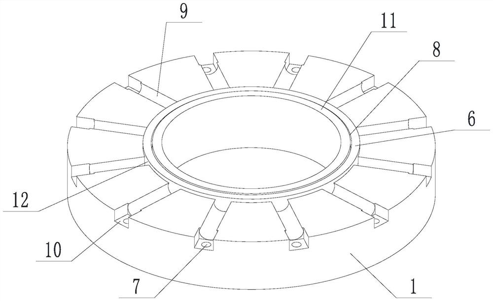
[0038] In this embodiment, the inner diameter side of the end surface of the static ring body 1 is provided with an annular protrusion 12 to form a high surface of the ring, and the outer diameter side of the end surface of the static ring body 1 automatically forms a lower surface of the ring; the inner diameter side of the flat foil 2 is assembled on the said On the annular protrusion 12.
[0039]...
Embodiment 2
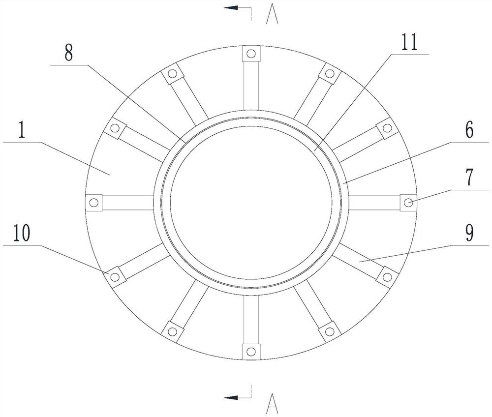
[0046] Such as Figure 1 to Figure 7 In the shown dry gas seal structure with controllable end face stiffness, on the basis of Embodiment 1, an annular groove 8 is arranged on the annular protrusion 12, and the inner diameter side of the flat foil 2 is arranged in contact with the annular groove 8, the first extension part 201 is matched with the first extension part 201, and the first extension part 201 is held in the annular groove 8 by clearance fit. A second extension 202 is provided on the outer diameter side of the flat foil 2 , and the extension length of the second extension 202 in the axial direction is smaller than the minimum height of the annular protrusion 12 .
[0047] In this embodiment, the annular groove 8 divides the annular protrusion 12 into a seal dam 11 near the inner diameter end and a support dam 6 near the outer diameter end; the height of the seal dam 11 is greater than the height of the support dam 6, and the seal dam 11 and the support The height d...
Embodiment 3
[0052] A dry gas seal structure with controllable end face stiffness, on the basis of any of the above-mentioned embodiments, such as Figure 1 to Figure 11 As shown, the end surface of the static ring body 1 is provided with a plurality of annular evenly distributed arc-shaped grooves 9 , and the axes of the arc-shaped grooves 9 are distributed along the radial direction of the static ring body 1 . The elastic part 3 is clearance fit in the arc groove 9, and the elastic part 3 is partially exposed to the plane where the end face of the static ring body 1 is located; in this embodiment, the elastic part 3 is partially exposed along the axial direction of the static ring body 1, which ensures the Effective contact of the flat foil 2.
[0053] Such as Figure 9 As shown, the arc groove 9 is an arc groove with a central angle greater than 180°, that is Figure 9 α is less than 180°.
[0054] In the present embodiment, the elastic member 3 is as Figure 8 Compressible spring s...
PUM
 Abstract
Description
Claims
Application Information
 - R&D
- Intellectual Property
- Life Sciences
- Materials
- Tech Scout
- Unparalleled Data Quality
- Higher Quality Content
- 60% Fewer Hallucinations
Browse by: Latest US Patents, China's latest patents, Technical Efficacy Thesaurus, Application Domain, Technology Topic, Popular Technical Reports.
© 2025 PatSnap. All rights reserved.Legal|Privacy policy|Modern Slavery Act Transparency Statement|Sitemap|About US| Contact US: help@patsnap.com


