
Generated gas analysis method and generated gas analysis device

A technology of gas analysis and gas composition, which is applied in the direction of measuring devices, analytical materials, and thermal analysis of materials, etc. It can solve problems such as the detection signal drop of the measured object, and achieve the effect of high-precision operation efficiency and high operation efficiency

Active Publication Date: 2020-06-19
HITACHI HIGH TECH SCI CORP
View PDF2 Cites 0 Cited by
  • Summary
  • Abstract
  • Description
  • Claims
  • Application Information

AI Technical Summary

Problems solved by technology

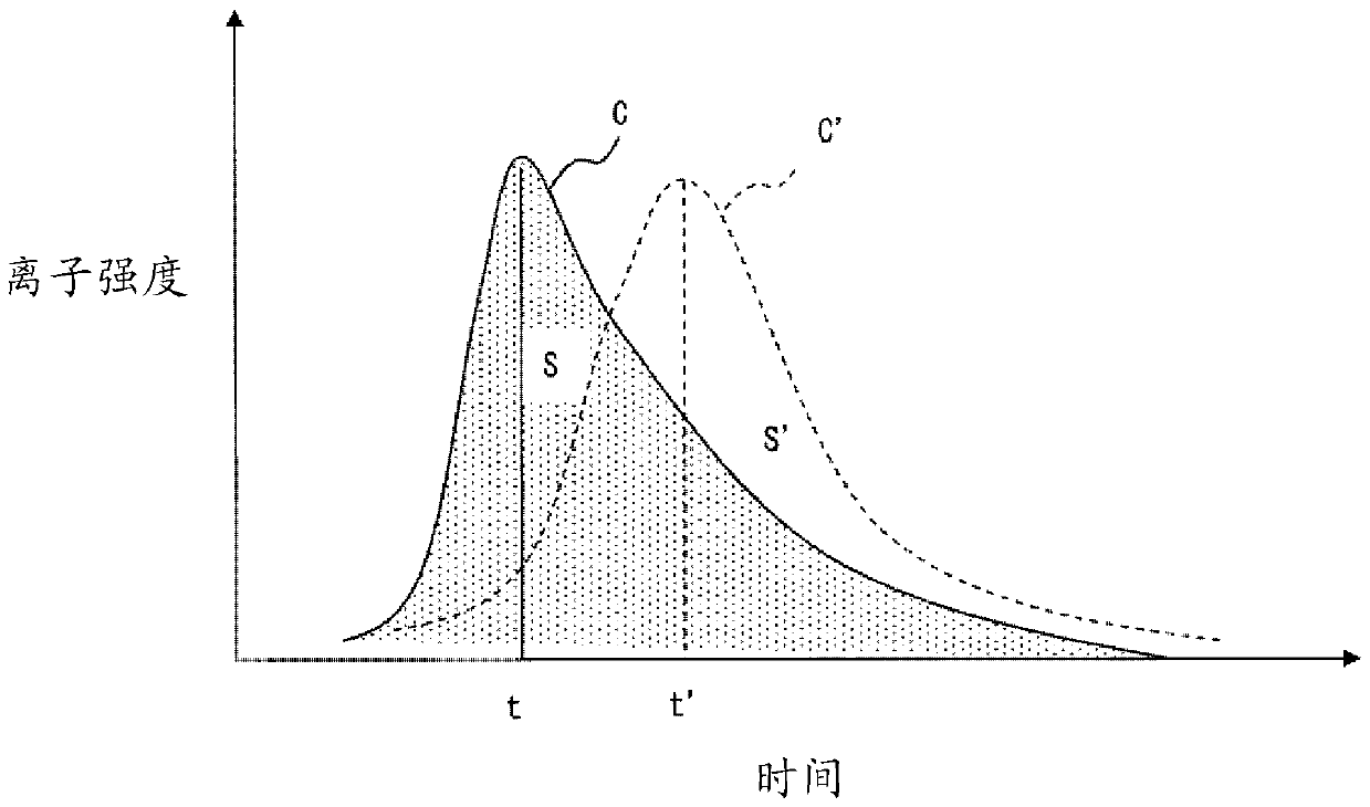
However, if the gas component contains subcomponents that are not the object of measurement, when a large amount of gas components are generated, the subcomponents will be ionized in large quantities, but the components of the measurement object that were originally intended to be ionized are not sufficiently ionized, and the measurement object The detection signal drops instead (ion suppression)

Method used


Image

  • Generated gas analysis method and generated gas analysis device
  • Generated gas analysis method and generated gas analysis device
  • Generated gas analysis method and generated gas analysis device

Examples


Embodiment Construction

[0042] Hereinafter, embodiments of the present invention will be described with reference to the drawings. figure 1 is a perspective view showing the configuration of a generated gas analysis device 200 according to an embodiment of the present invention, figure 2 is a perspective view showing the structure of the gas generating unit 100, image 3 is a longitudinal cross-sectional view along the axis O showing the structure of the gas generating unit 100, Figure 4 It is a cross-sectional view along the axis O showing the structure of the gas generating unit 100 .

[0043] The generated gas analysis device 200 includes a main body 202 serving as a frame, a box-shaped gas generating unit mounting unit 204 attached to the front of the main body 202 , and a computer (control unit) 210 for overall control. The computer 210 has a CPU for processing data, a storage unit for storing computer programs and data, a monitor, an input unit such as a keyboard, and the like. The comput...


PUM


Abstract

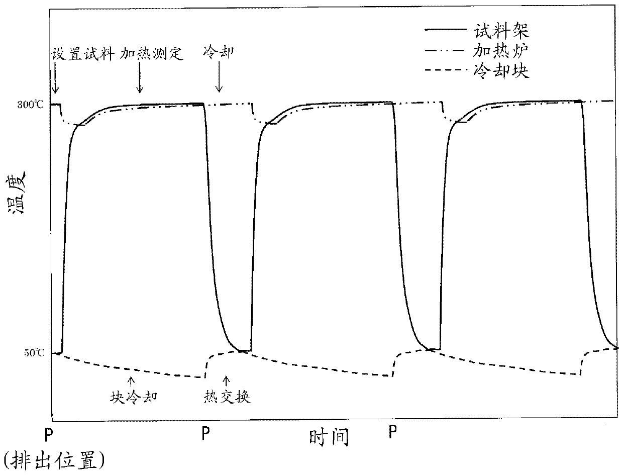
The generated gas analysis device includes: a sample holder, a heating unit for heating a sample to generate gas components, an ion source for ionizing gas components to generate ions, a mass analyzer for mass analysis of ions to detect gas components, and a supply gas component The gas flow path that flows through the mixed gas of the carrier gas that leads it to the mass analyzer has a discharge flow adjustment step that adjusts the discharge flow rate of the mixed gas in the branch path to the outside in the generated gas analysis method; a cooling step that makes the sample The frame contacts the cooling part to cool it; the correction process uses a standard sample containing gas components as the measurement object, (1) corrects the spectral position of the mass spectrum, (2) calculates the sensitivity correction coefficient Cs=Ss / S, (3 ) Calculate the heating correction coefficient H=t / ts for correcting the heating rate of the sample in the heating section when measuring the gas component of the actual sample.

Description

technical field [0001] The present invention relates to a generated gas analysis method and a generated gas analysis device for ionizing gas components generated by heating a sample for mass analysis, identifying and quantifying the sample, and the like. Background technique [0002] In order to ensure the flexibility of the resin, plasticizers such as phthalates are contained in the resin, and the use of the four types of phthalates is restricted after 2019 in accordance with the European Regulation on Specific Hazardous Substances (RoHS). Therefore, it is necessary to identify and quantify the phthalates in the resin. [0003] Since phthalate is a volatile component, it can be analyzed using conventionally known evolved gas analysis (EGA: Evolved Gas Analysis). The generated gas analysis is a method of analyzing gas components generated by heating a sample with various analysis devices such as a gas chromatograph and a mass spectrometer. [0004] In addition, since the s...

Claims


Application Information

Patent Timeline
Patent Type & Authority Patents(China)
IPC IPC(8): G01N30/86G01N30/02G01N30/72
CPCG01N30/02G01N30/72G01N30/8668G01N25/4826G01N30/7206
Inventor 秋山秀之山田健太郎渡边将史竹内俊公丸冈干太郎
Owner HITACHI HIGH TECH SCI CORP
Learn More