

Method for identifying non-bright spot oil reservoir in third AVO bright spot characteristic reservoir stratum zone
A bright spot, oil reservoir technology, applied in seismology, measuring devices, instruments, etc. for logging records, can solve the problem of not establishing the corresponding relationship of the reservoir wave impedance model, and achieve the effect of reducing exploration risk and improving accuracy
- Summary
- Abstract
- Description
- Claims
- Application Information
AI Technical Summary
Problems solved by technology
Method used
Image

Examples
Embodiment 1
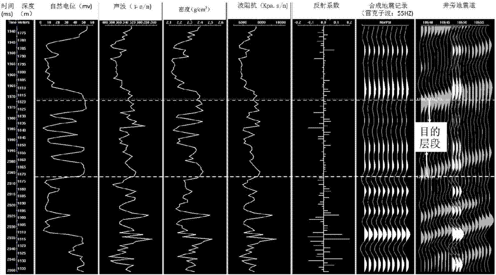
[0054] The area of the 3D seismic data in the work area is 5.6km 2 , A1 exploration well has been drilled, and oil reservoirs have been discovered in three types of AVO "bright spot" characteristic reservoir areas. There are at most four sets of sand bodies in the thin interbeds of sand and shale in the target layer of the work area. Forward modeling has confirmed that the seismic reflection wave at the top of the thin interbeds is relatively less interfered by the reflection of the thin interbeds, making a relatively small sand body formed on the top of the thin interbeds. Strong seismic reflection events. If the sand body on the top of the thin interbed contains oil, the wave impedance difference between the upper and lower formations on the top will increase, forming a "bright spot" characteristic event on the top; if the middle sand body in the thin interbed contains oil, the thin interbed contains oil The sandstone reservoir is disturbed by the reflection wave of the s...
PUM
 Abstract
Description
Claims
Application Information