
Laser Arrays for 3D Imaging

A laser array, 3D technology, applied in the field of laser array, can solve the problem of low irrelevance of VCSEL light source, and achieve the effect of high irrelevance

Active Publication Date: 2019-04-09
SHENZHEN ORBBEC CO LTD
View PDF7 Cites 0 Cited by
  • Summary
  • Abstract
  • Description
  • Claims
  • Application Information

AI Technical Summary

Problems solved by technology

[0005] In order to solve the problem of low irrelevance of the VCSEL light source used for 3D imaging, the present invention proposes a VCSEL array light source for 3D imaging

Method used


Image

  • Laser Arrays for 3D Imaging
  • Laser Arrays for 3D Imaging
  • Laser Arrays for 3D Imaging

Examples


Embodiment Construction

[0032] The present invention will be further described below with reference to the accompanying drawings and in combination with preferred embodiments.

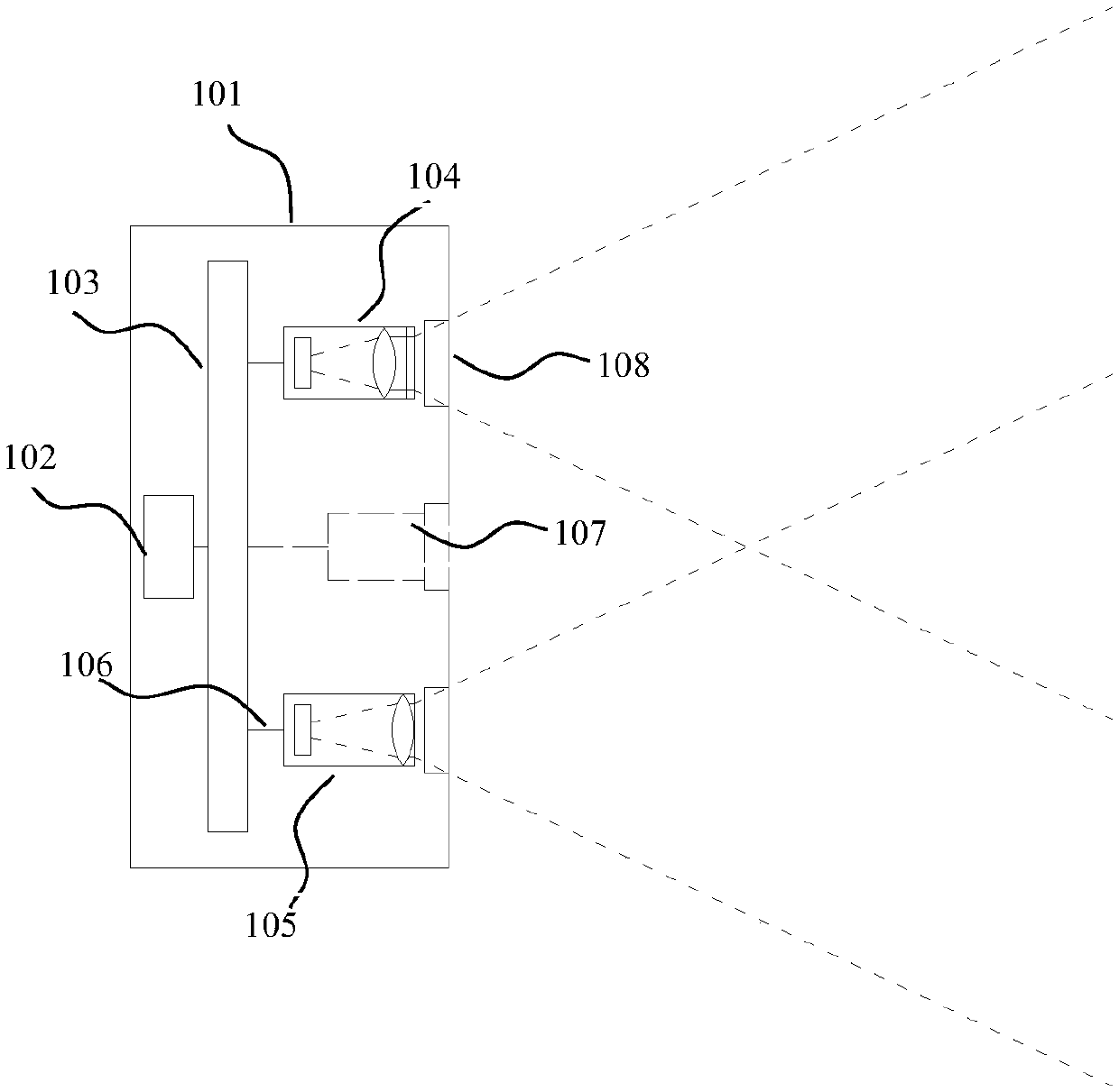
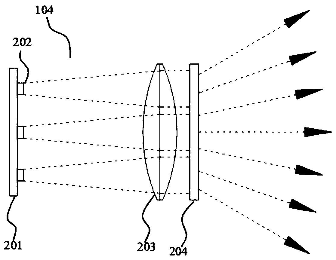
[0033] The present invention proposes a laser array for 3D imaging, and proposes a corresponding laser projection device and 3D imaging device based on the laser array. The 3D imaging device here is also called a depth camera, and the image of the object captured by the depth camera is The value on each pixel in represents the depth value between the corresponding point in space and the depth camera. In the following description, the laser array, laser projection device and depth camera will be described as examples, but it does not mean that this laser array can only be applied in the depth camera, any other device that uses this solution directly or indirectly should be included in the protection scope of the present invention.

[0034] figure 1 The side schematic diagram of the depth camera based on structured light is s...


PUM


Abstract

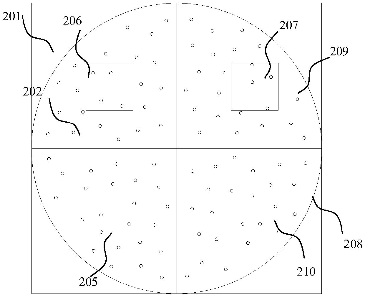
The invention discloses a laser array for 3D imaging, a pattern design method of the laser array for 3D imaging, a laser projection device and a 3D imaging device, wherein the laser array for 3D imaging includes: A plurality of VCSEL light sources arranged in the form of a two-dimensional array; the arrangement of the two-dimensional array is generated by rotating and replicating at least one sub-array, and the arrangement of the two-dimensional array obtained in the form of simply rotating and replicating the sub-array The sub-regions containing any other quadrant along any direction are irrelevant, and the two-dimensional array corresponds to the distribution of VCSEL light sources, so the VCSEL light sources distributed on the surface of the semiconductor substrate have extremely high irrelevance. The problem of low irrelevance of the VCSEL light source used for 3D imaging in the prior art is solved, and the laser array of the present invention is mainly used in depth cameras.

Description

technical field [0001] The invention relates to the fields of optics and electronics technology, in particular to a laser array for 3D imaging. Background technique [0002] 3D imaging, especially the 3D imaging technology used in the consumer field, will continue to impact or even replace the traditional 2D imaging technology. In addition to the 2D imaging capability of the target object, the 3D imaging technology can also obtain the depth information of the target object. According to the depth information 3D scanning, scene modeling, gesture interaction and other functions can be further realized. Depth cameras, especially structured light depth cameras or TOF (time-of-flight) depth cameras, are currently hardware devices commonly used for 3D imaging. [0003] The core component of the depth camera is the laser projection module. According to the different types of depth cameras, the structure and function of the laser projection module are also different. For example, t...

Claims


Application Information

Patent Timeline
Patent Type & Authority Patents(China)
IPC IPC(8): H01S5/42G03B15/02G03B35/00
CPCH01S5/423G03B15/02G03B35/00
Inventor 王兆民闫敏许星
Owner SHENZHEN ORBBEC CO LTD
Learn More