A Control Method of Voltage Source Inverter Constructing Rotating Coordinate System for Zero-axis Vector
A technology of voltage source inverter and rotating coordinate system, which is applied in the direction of electrical components, output power conversion device, AC power input conversion to DC power output, etc. Stable operation and other issues to achieve good control effect
- Summary
- Abstract
- Description
- Claims
- Application Information
AI Technical Summary
Problems solved by technology
Method used
Image
Examples
Embodiment Construction
[0029] The technical solutions of the present invention will be further described below in conjunction with the accompanying drawings and specific embodiments.
[0030] In this embodiment, a three-phase four-leg voltage source inverter with a capacity of 40kvar and a rated output current of 60A is taken as an example, and the DC side voltage is 700V.
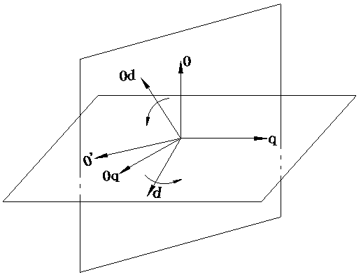
[0031] Such as figure 1 , 2 As shown, the embodiment of the present invention includes, including the following steps:
[0032] Use the current Hall sensor to collect the three-phase grid current i a i b i c , according to the formula to get the zero axis current i 0 ;Calculated as follows:
[0033]
[0034] Construct a 0-0' coordinate system orthogonal to the zero axis through the second-order generalized integrator module 1, and construct a zero-axis current i on the 0' axis 0 Orthogonal virtual current vector i 0 ’, with i 0 Synthesize the new zero-axis current vector I 0 ;Construct calculation formula as follows...
PUM
 Abstract
Description
Claims
Application Information
 - R&D
- Intellectual Property
- Life Sciences
- Materials
- Tech Scout
- Unparalleled Data Quality
- Higher Quality Content
- 60% Fewer Hallucinations
Browse by: Latest US Patents, China's latest patents, Technical Efficacy Thesaurus, Application Domain, Technology Topic, Popular Technical Reports.
© 2025 PatSnap. All rights reserved.Legal|Privacy policy|Modern Slavery Act Transparency Statement|Sitemap|About US| Contact US: help@patsnap.com


