

Dynamic calibration method and method for infrared proximity transducer
An infrared proximity and dynamic calibration technology, which is applied in the direction of instruments, telephone communications, electrical components, etc., can solve the problems of infrared signal intensity changes, easy to be affected by oil pollution, and affect normal work.
Inactive Publication Date: 2017-07-21
深圳市君利信达科技有限公司
View PDF6 Cites 14 Cited by
- Summary
- Abstract
- Description
- Claims
- Application Information
AI Technical Summary
Problems solved by technology
[0005] The main purpose of the present invention is to propose a dynamic calibration method and device for an infrared proximity sensor, aiming to solve the problem that the existing infrared proximity sensor is easily affected by oil pollution, resulting in a change in the intensity of the infrared signal, thereby affecting its normal operation
Method used
View moreImage
Smart ImageViewing Examples

Examples
Embodiment 3
[0119] Based on another aspect of the present invention, the present invention also provides a mobile terminal having the above-mentioned dynamic calibration device for an infrared proximity sensor. Using the calibration function module of the mobile terminal, especially the offset calibration function unit, and the preset oil pollution threshold, the dynamic anti-oil pollution algorithm is realized by comparing the infrared signals in real time, so as to avoid the oil pollution caused by the infrared sensor when the user is using the mobile phone. factors, resulting in failure to turn on the screen or entering the anti-mistouch mode by mistake.
Login to View More PUM
 Abstract
The invention discloses a dynamic calibration method and method for an infrared proximity transducer. The method comprises the following steps of calling a calibration function module of a mobile terminal to calibrate a ground noise value of the infrared proximity transducer to a target signal value To when no shelter exists; presetting an initial proximity threshold value Hi, an initial distant threshold value Lo and an oil contamination threshold Max-N of the infrared proximity transducer; obtaining a real-time infrared signal S of the infrared proximity transducer and comparing the real-time infrared signal S with the oil contamination threshold Max-N when the shelter exists; when the real-time infrared signal S is not smaller than the oil contamination threshold Max-N, judging that the oil contamination exists and computing to obtain a corrected distant threshold value Lo+Od; and comparing the real-time infrared signal S with the corrected distant threshold value Lo+Od, when the real-time infrared signal S is smaller than the corrected distant threshold value Lo+Od, calibrating the target signal value To to the real-time infrared signal S. The invention aims at solving the technical problem that the existing infrared proximity transducer is easily affected by the oil contamination to cause change of intensity of the infrared signal due.
Description
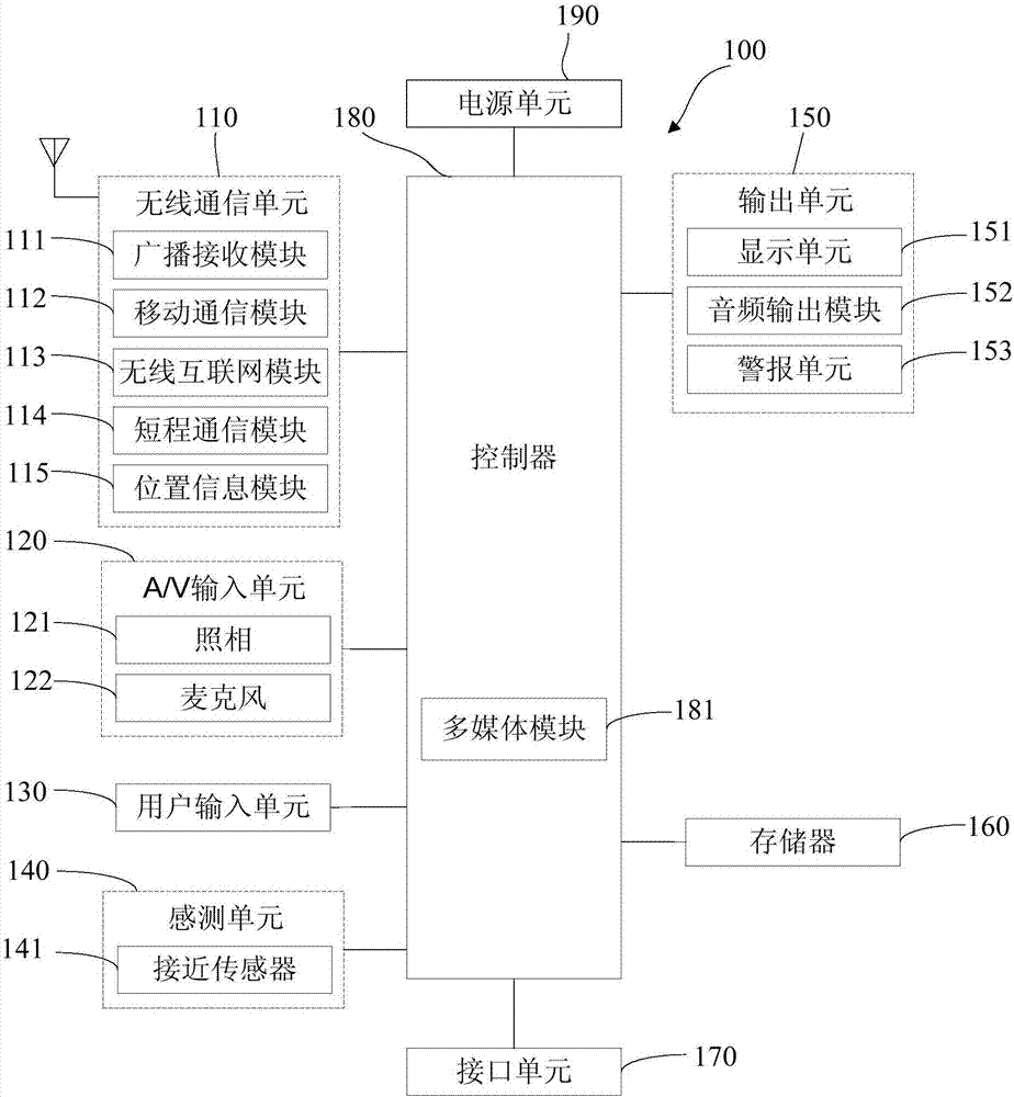
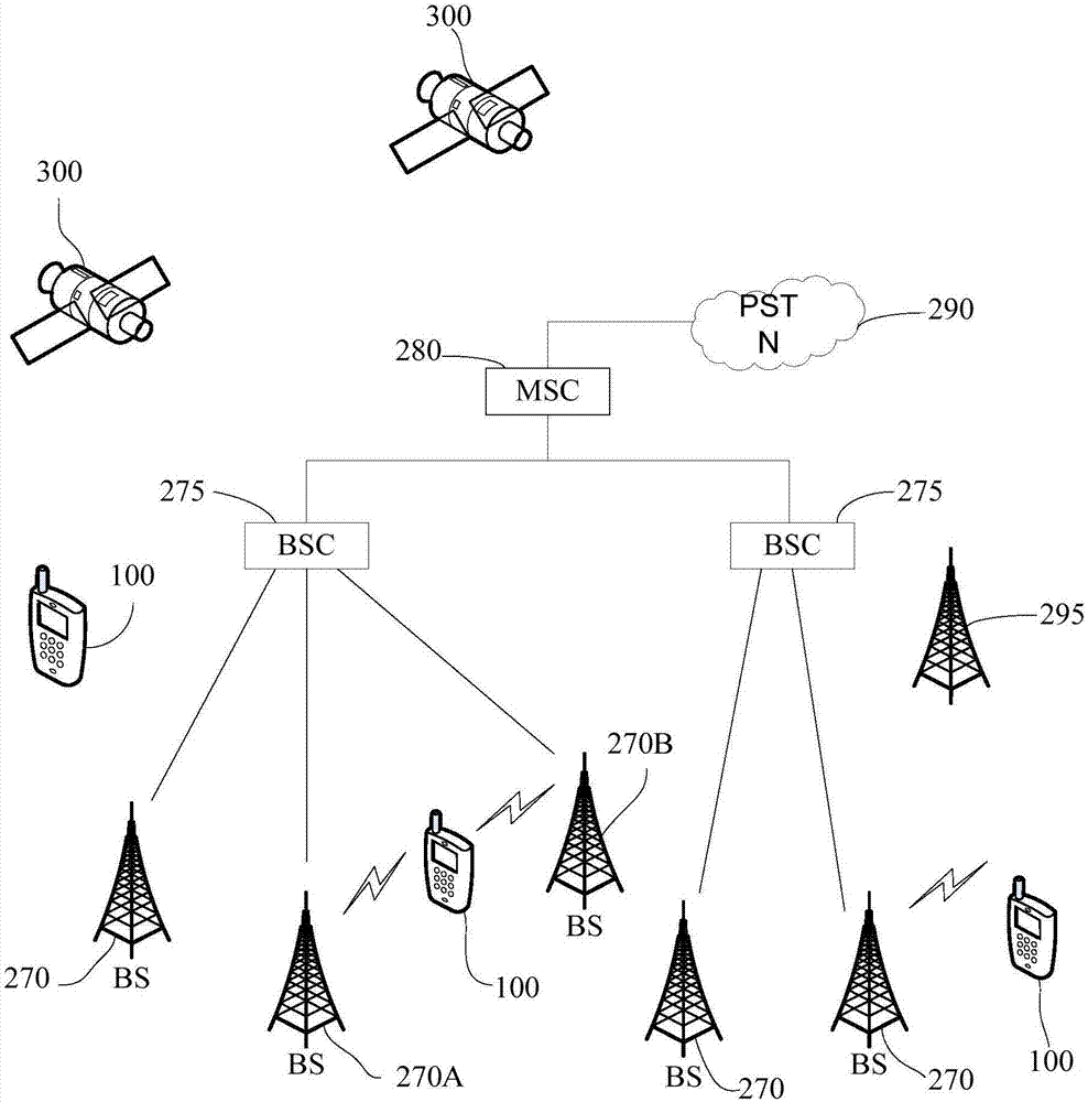
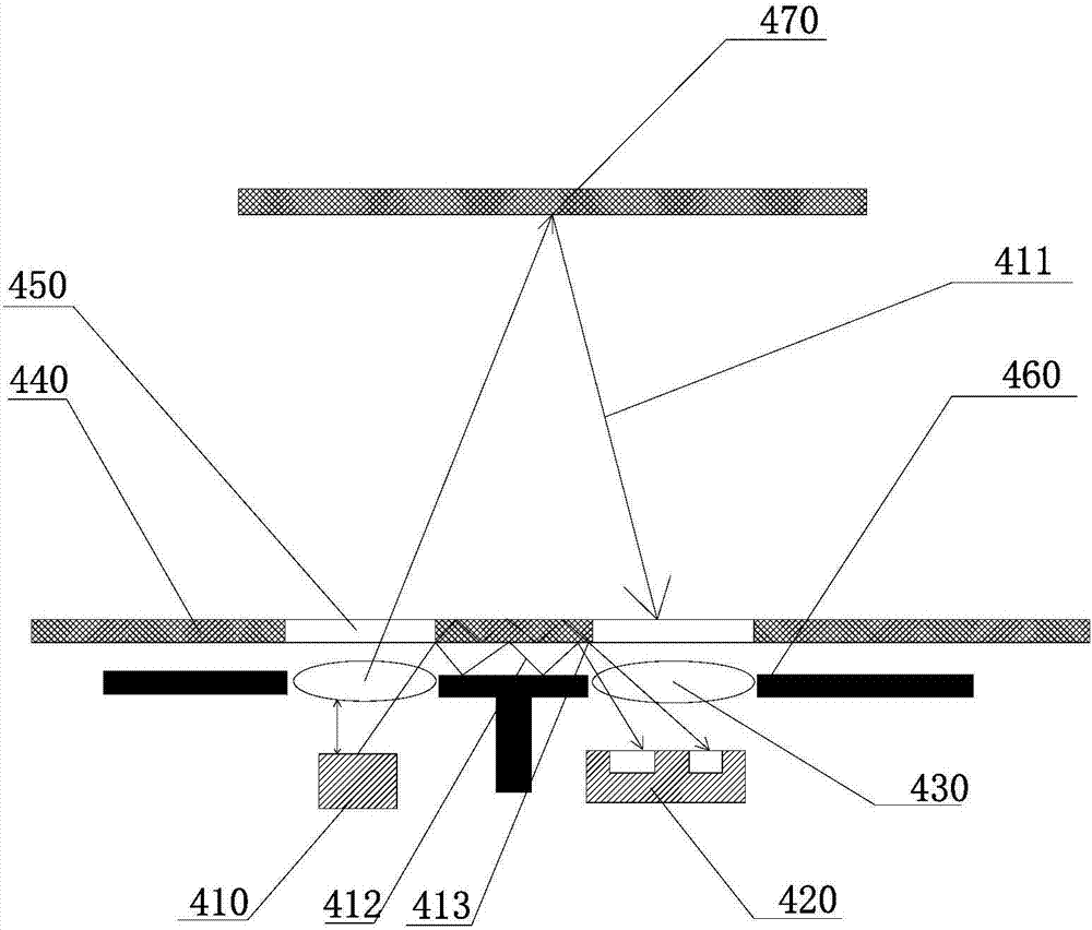
technical field [0001] The invention relates to the technical field of mobile terminals, in particular to a dynamic calibration method and device for an infrared proximity sensor. Background technique [0002] Existing mobile terminals such as mobile phones are usually provided with ambient light sensors and proximity sensors. An ambient light sensor optimizes LCD display visibility based on light levels. That way, you can adjust the brightness of the backlight depending on whether you're in a dimly lit area or in bright light. Proximity sensors are used to turn off the display's backlight when brought close to your head and disable the touch function, preventing your cheek from accidentally triggering the keys of the mobile terminal. The function of ambient light sensor and proximity sensor is to reduce power consumption and extend battery life. In particular, smartphone calls are undoubtedly a very common and high-frequency scene for users. In order to prevent accidenta...
Claims
Login to View More Application Information
Patent Timeline
 IPC IPC(8): H04M1/725G01V13/00
CPCG01V13/00H04M1/72403H04M1/72448
Inventor鲍琦
Owner深圳市君利信达科技有限公司