Cutting blade

A technology of cutting inserts and inserts, applied in cutting inserts, turning equipment, accessories of tool holders, etc., can solve the problems of reducing the cutting life of cutting inserts, reducing the structural strength of cutting inserts, and the difference of cutting conditions, etc. Effects of vibration, improved cutting accuracy and service life

Active Publication Date: 2017-07-25
ZHUZHOU CEMENTED CARBIDE CUTTING TOOLS CO LTD
View PDF10 Cites 3 Cited by
  • Summary
  • Abstract
  • Description
  • Claims
  • Application Information

AI Technical Summary

Problems solved by technology

[0002] When the cutting blade is cutting, the cutting force is mainly borne by the main cutting edge, and the auxiliary cutting edge only bears part of the cutting force. When cutting with a single-segment straight main cutting edge, the cutting force can only be directed in one direction, and the blade wears rapidly and even It is prone to chipping, which greatly reduces the cutting life of the cutting insert, especially when the cutting insert is used for cutting with a large overhang length, because the main cutting force of the cutting insert is too concentrated, resulting in a large radial force, the cutting deflection increases during cutting, Intensified vibration, in order to ensure the surface quality of the cutting blade and the life of the cutting blade, cutting can only be completed under low cutting parameters, resulting in a reduction in the processing efficiency of the cutting blade
[0003] In the prior art, in order to improve the cutting performance, the cutting edge of the cutting blade is usually designed as a multi-section cutting edge with complex angles. Although the force distribution of the cutting edge of the cutting blade can be improved, the main and auxiliary cutting edges are designed to have the same complex angle. The blade shape and groove structure reduce the structural strength of the cutting blade, and in order to ensure that the main and auxiliary cutting edges can perform normal cutting, the rotation range of the cutting angle of the cutting blade is very limited during installation; In high-efficiency cutting, the cutting conditions of the main and auxiliary cutting edges are quite different. When the main and auxiliary cutting edges with the same groove structure participate in cutting at the same time, it is difficult to ensure that the main and auxiliary cutting edges can exert the best cutting performance at the same time. Usually, the The structural form that guarantees the performance of the main cutting edge is likely to cause a mismatch between the cutting ability of the secondary cutting edge and the cutting working conditions, resulting in excessive wear of the secondary cutting edge and low service life

Method used


Image

  • Cutting blade
  • Cutting blade
  • Cutting blade

Examples


Embodiment Construction

[0031] The present invention will be further described in detail below in conjunction with the accompanying drawings and specific embodiments.

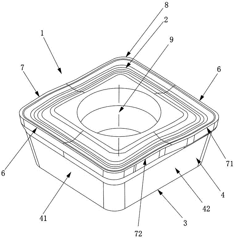
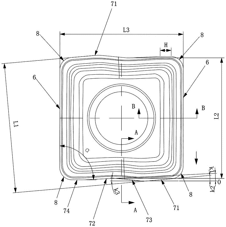
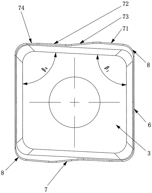
[0032] Figure 1 to Figure 5The first embodiment of the cutting insert of the present invention is shown, the cutting insert of this embodiment includes a plate-shaped insert body 1, the insert body 1 is surrounded by an upper surface 2, a lower surface 3 and a side 4 connecting the upper and lower surfaces, The upper surface 2 intersects with the side 4 to form a plurality of cutting units with the same structure. The cutting edge unit includes a minor cutting edge 6, a major cutting edge 7 and a corner cutting edge 8 between the minor cutting edge 6 and the major cutting edge 7. The cutting edge 6 and the main cutting edge 7 are alternately arranged in the circumferential direction of the insert body 1, and the main cutting edge 7 includes a first cutting edge 71, a second cutting edge 72 and a transitional cutting edge connecting t...


PUM


Abstract

The invention discloses a cutting blade. The cutting blade comprises a plate-shaped blade body which is encircled by an upper surface, a lower surface and a side surface, wherein the upper surface and the lower surface are connected through the side surface; the upper surface and the side surface are intersected to form a plurality of cutting units which have the same structure; a cutting edge unit comprises a secondary cutting edge, a main cutting edge, and a corner cutting edge which is positioned between the secondary cutting edge and the main cutting edge; the secondary cutting edge and the main cutting edge are alternatively arranged in the circumference of the blade body; the main cutting edge comprises a first cutting edge, a second cutting edge, and a transition cutting edge for connecting the first cutting edge and the second cutting edge; the surface, vertical to the feeding direction of the cutting blade in hole drilling processing, is a reference surface O; in the upper surface direction, the secondary cutting edge is provided with one cutting slope, and the first cutting edge, the second cutting edge and the transition cutting edge are correspondingly provided with the cutting slope k1, k2 and k3 which meet the formula seeing the description. The cutting blade has the advantages of being high in cutting accuracy, small in cutting vibration, long in service life, etc.

Description

technical field [0001] The invention relates to the technical field of metal cutting, in particular to a cutting blade. Background technique [0002] When the cutting blade is cutting, the cutting force is mainly borne by the main cutting edge, and the auxiliary cutting edge only bears part of the cutting force. When cutting with a single-segment straight main cutting edge, the cutting force can only be directed in one direction, and the blade wears rapidly and even It is prone to chipping, which greatly reduces the cutting life of the cutting insert, especially when the cutting insert is used for cutting with a large overhang length, because the main cutting force of the cutting insert is too concentrated, resulting in a large radial force, the cutting deflection increases during cutting, The vibration is aggravated. In order to ensure the surface quality of the cutting blade and the life of the cutting blade, the cutting can only be completed under low cutting parameters, ...

Claims


Application Information

Patent Timeline
Patent Type & Authority Applications(China)
IPC IPC(8): B23B27/00
CPCB23B27/00B23B2200/28
Inventor 江爱胜王社权刘敏李屏汤爱民项兴东王鹏
Owner ZHUZHOU CEMENTED CARBIDE CUTTING TOOLS CO LTD
Why Eureka
Try Eureka