Rotary machining cutter

A technology of rotary machining and rotary cutter, applied in manufacturing tools, metal processing equipment, tools for lathes, etc., can solve the problems of inconsistent tool runout accuracy and static accuracy, inability to achieve low runout finishing cutting, poor structural strength, etc. , to achieve highly consistent static runout accuracy, ensure the quality of the machined surface, and improve the positioning strength and rigidity.

Active Publication Date: 2016-02-17
ZHUZHOU CEMENTED CARBIDE CUTTING TOOLS CO LTD
View PDF6 Cites 1 Cited by
  • Summary
  • Abstract
  • Description
  • Claims
  • Application Information

AI Technical Summary

Problems solved by technology

In some processing occasions, the end or side runout of the cutting blade on the rotary tool is required to reach 0.001mm, but due to the size of the cutter body and cutting blade of the rotary tool being limited by the manufacturing capacity and the existence of assembly clearance, the runout is difficult To achieve such a high-precision requirement, in order to meet the processing needs, it is a relatively common structure in the finishing tool of the prior art to set one or more tool pockets with a run-out adjustment structure in the tool holder. After the tool holder is provided with a run-out adjustment structure, The static accuracy of the tool holder can be improved after each adjustment, but the positioning scheme structure in the prior art and the multi-structure strength of the tool attachment are poor, and cutting vibration is prone to occur during cutting, resulting in inconsistent tool runout accuracy and static accuracy during cutting, which cannot achieve true accuracy. Low run-out finishing cutting in the sense

Method used


Image

  • Rotary machining cutter
  • Rotary machining cutter
  • Rotary machining cutter

Examples


Embodiment Construction

[0032] The present invention will be further described in detail below in conjunction with the accompanying drawings and specific embodiments.

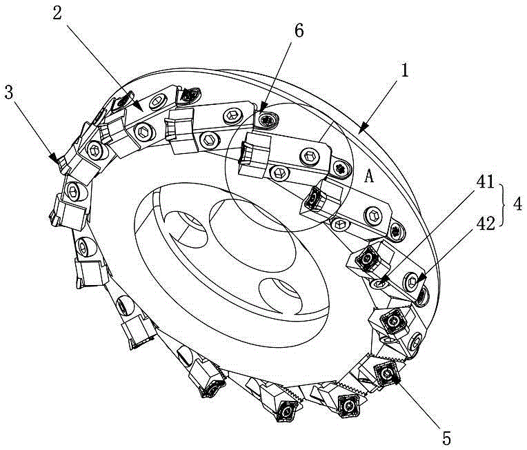
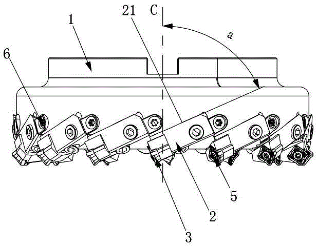
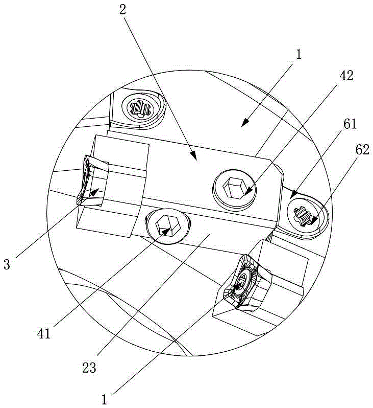
[0033] Figure 1 to Figure 7 The first embodiment of the rotary machining tool of the present invention is shown. The rotary machining tool of this embodiment includes a rotary cutter body 1, and a knife groove 11 is opened on the outer edge of the front end of the rotary cutter body 1, and the inside of the knife groove 11 is fastened by a tool holder. The assembly 4 is equipped with a tool holder 2, the head of the tool holder 2 is equipped with a cutting blade 3 through the blade fastener 5, and an adjustment structure 6 is also installed in the knife groove 11, and the adjustment structure 6 is located on the tail surface of the tool holder 2 Between the tail positioning surface of the tool groove 11, the surface between the tail surface and the end surface of the tool holder 2 on the tool holder 2 is the circumferential surface o...


PUM


Abstract

The invention discloses a rotary machining cutter which comprises a rotary cutter body, wherein cutter slots are formed in the outer edge at the front end of the rotary cutter body; cutter holders are mounted in the cutter slots through cutter holder fastening components; cutting blades are mounted at the head parts of the cutter holders through cutting blade fasteners; adjusting structures are also mounted in the cutter slots; the adjusting structures are located between the tail part surfaces of the cutter holders and the tail part positioning surfaces of the cutter slots; all the surfaces, located between the tail part surfaces and the end surfaces of the cutter holders, of the cutter holders are circumferential surfaces of the cutter holders; each cutter holder fastening component comprises at least two cutter holder fasteners; and the cutter holders are locked by the cutter holder fasteners in different directions of the circumferential surfaces of the cutter holders. The rotary machining cutter provided by the invention has the advantages of positioning stability, strong vibration resistance, long service life, high machining precision and the like.

Description

technical field [0001] The invention relates to the field of metal cutting, in particular to a rotary machining tool. Background technique [0002] With the development of the metal processing manufacturing industry, the requirements for the surface finish of the processing are getting higher and higher. In the cutting operation of the rotary tool with multiple cutting blades, in order to improve the surface finish of the processing, the end or side of the cutting blade is required to have Higher positioning accuracy. In some processing occasions, the runout of the end or side of the cutting blade on the rotary tool is required to reach 0.001mm, but due to the size of the cutter body and cutting blade of the rotary tool being limited by the manufacturing capacity and the existence of assembly clearance, the runout is difficult To achieve such a high-precision requirement, in order to meet the processing needs, it is a relatively common structure in the finishing tool in the...

Claims


Application Information

Patent Timeline
Patent Type & Authority Applications(China)
IPC IPC(8): B23B27/16B23B27/00
CPCB23B27/00B23B27/16B23B2205/04
Inventor 汤爱民江爱胜刘敏
Owner ZHUZHOU CEMENTED CARBIDE CUTTING TOOLS CO LTD
Why Eureka
Try Eureka