A finishing milling tool

A milling tool and milling technology, which is applied in the direction of milling cutters, manufacturing tools, metal processing equipment, etc., can solve the problems of lower precision requirements, difficult finishing machining, and easy vibration, so as to reduce cutting force and cutting vibration and ensure machining Surface quality, the effect of eliminating residual steps

Active Publication Date: 2016-08-31
ZHUZHOU CEMENTED CARBIDE CUTTING TOOLS CO LTD
View PDF5 Cites 0 Cited by
  • Summary
  • Abstract
  • Description
  • Claims
  • Application Information

AI Technical Summary

Problems solved by technology

[0002] Milling tools usually adopt a structure with only one finishing blade or two types of finishing blades and main cutting blades to realize the finishing of milling tools. With the rapid development of the manufacturing industry, the finishing milling tools require more and more The higher the processing quality, the surface roughness of the processed workpiece is even required to be below Ra0.4. With such a high surface quality requirement, even if there is a small oblique angle with the horizontal direction when the linear cutting edge is fed, it will still cause The quality of the machined surface is not ideal. In theory, when the straight cutting edge is completely horizontal, it can meet the requirements of finishing. However, due to the existence of manufacturing and assembly errors, it is difficult to make the straight cutting edges of multiple finishing milling inserts on the milling tool completely horizontal. Therefore, it is difficult to realize the finishing of milling tools with straight cutting edges, and it is difficult to be widely used.
[0003] In order to facilitate use and reduce manufacturing difficulty in the industry, a finishing milling insert with an arc-shaped cutting edge can be set on the milling tool. When using an arc-shaped cutting edge for finishing, the precision requirements for manufacturing and assembly can be reduced. In order to improve the versatility, but in the actual use process, in order to improve the quality of the processed surface, the radius of the arc-shaped cutting edge often needs to reach 500mm or more. The internal force is relatively large, and it is easy to generate vibration during cutting. At the same time, when the cutting width of the workpiece is larger than the diameter of the milling cutter head during face milling, multiple cuttings are required to complete the surface processing. When , the two adjacent milling surfaces are easy to form steps

Method used


Image

  • A finishing milling tool
  • A finishing milling tool
  • A finishing milling tool

Examples


Embodiment Construction

[0030] The present invention will be further described in detail below in conjunction with the accompanying drawings and specific embodiments.

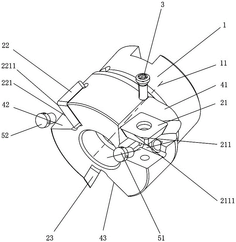
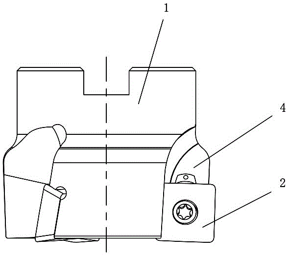
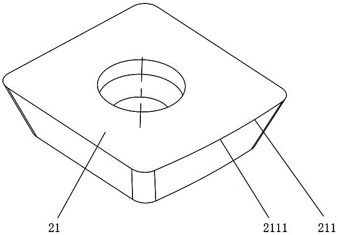
[0031] Figure 1 to Figure 8 The first embodiment of the finishing milling tool of the present invention is shown, the finishing milling tool comprises a cutter body 1, a cutting tool set 2 and a knife set fastener 3, the cutter body 1 is provided with a sipe 4, and the cutting tool The group 2 is installed in the knife groove 4 through the knife group fastener 3. The cutting tool group 2 includes a first fine cutting blade 21 and a second fine cutting blade 22. The first fine cutting blade 21 is provided with a first arched cutting blade. Edge 211, the second fine cutting blade 22 is provided with the second arched cutting edge 221 corresponding to the first arched cutting edge 211, that is, if the peripheral cutting surface of the first fine cutting blade 21 is provided with the first arched cutting edge Edge 211, the second arc cu...


PUM


Abstract

The invention discloses a finishing milling cutter, which comprises a cutter body, a cutting cutter group and a cutter group fastener, the cutter body is provided with a slit, and the cutting cutter group is installed through the cutter group fastener In the sipe, the cutting tool set includes a first fine cutting blade and a second fine cutting blade, the first fine cutting blade is provided with a first arcuate cutting edge, and the second fine cutting blade is provided with There is a second arched cutting edge corresponding to the first arched cutting edge, the radius of curvature of the middle high convex point of the first arched cutting edge is R, and the second arched cutting edge is far away from the The radius of curvature at the endpoint of one end of the central axis of rotation of the cutter body is r, and r

Description

technical field [0001] The present invention relates to cutting tools, in particular to a finishing milling tool. Background technique [0002] Milling tools usually adopt a structure with only one finishing blade or two types of finishing blades and main cutting blades to realize the finishing of milling tools. With the rapid development of the manufacturing industry, the finishing milling tools require more and more The higher the processing quality, the surface roughness of the processed workpiece is even required to be below Ra0.4. With such a high surface quality requirement, even if there is a small oblique angle with the horizontal direction when the linear cutting edge is fed, it will still cause The quality of the machined surface is not ideal. In theory, when the straight cutting edge is completely horizontal, it can meet the requirements of finishing. However, due to the existence of manufacturing and assembly errors, it is difficult to make the straight cutting e...

Claims


Application Information

Patent Timeline
Patent Type & Authority Patents(China)
IPC IPC(8): B23C5/24
Inventor 江爱胜王社权刘敏赵志伟
Owner ZHUZHOU CEMENTED CARBIDE CUTTING TOOLS CO LTD
Why Eureka
Try Eureka