Grooving cutter

A cutting tool and grooving technology, applied to cutting blades, cutting tools for lathes, manufacturing tools, etc., can solve the problems of low clamping reliability, affecting the machining accuracy of parts, and large cutting vibration, etc., to improve repeat positioning accuracy , Improve clamping reliability and reduce cutting vibration

Active Publication Date: 2016-02-24
ZHUZHOU CEMENTED CARBIDE CUTTING TOOLS CO LTD
View PDF6 Cites 1 Cited by
  • Summary
  • Abstract
  • Description
  • Claims
  • Application Information

AI Technical Summary

Problems solved by technology

[0002] In the metal cutting processing industry, the blade is subjected to a large cutting force during the cutting and grooving process, resulting in a large cutting vibration. Usually, the clamping of the blade by the tool is concentrated on the part of the blade near the cutting edge, so that the During the cutting process, the rear end of the blade vibrates greatly, the clamping reliability is not high, and the tool is prone to wear and deformation, which affects the machining accuracy of the part
[0003] U.S. Patent No. 6,234,727B1 discloses a cutting tool. The first clamping surface of the tool can elastically move around the first elastic axis of rotation, and the second clamping surface can elastically move around the second elastic axis of rotation. The first clamping surface is opposite to the blade. The upper front end of the blade applies a clamping force, and the second clamping surface applies a clamping force to the upper rear end of the blade. Only when the first elastic axis and the second elastic axis are in line, the first clamping surface and the second clamping surface If the first elastic axis and the second elastic axis of rotation are not collinear, then the first clamping surface and the second clamping surface are not independent of each other, the degree of independence depends on the first elastic axis and the second elastic axis The closeness of the tool and the blade is greatly restricted. While ensuring the reliability of the clamping, it is difficult to ensure the complete independence of the two clamping surfaces.

Method used


Image

  • Grooving cutter
  • Grooving cutter
  • Grooving cutter

Examples


Embodiment Construction

[0030] The present invention will be further described in detail below in conjunction with the accompanying drawings and specific embodiments.

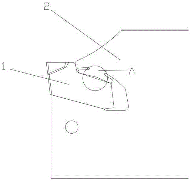
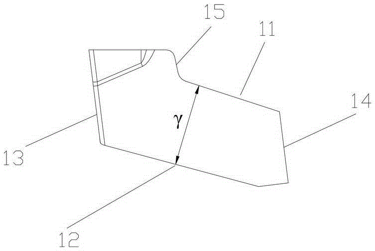
[0031] Figure 1 to Figure 5 A specific embodiment of a grooving tool of the present invention is shown. The grooving tool of this embodiment is a cutting tool, a grooving tool, a turning tool or a rotary type grooving milling tool, including a blade 1 and a cutter body 2, and the blade 1 Installed in the groove 25 of the cutter body 2 by means of elastic self-clamping, the blade 1 is composed of the blade flank 13, the blade tail surface 14 and the positioning part connecting the blade flank 13 and the blade tail surface 14, the blade 1 The positioning part includes an upper positioning part 11, a lower positioning part 12 and an upwardly protruding limiting part 15 connecting the upper positioning part 11 and the blade flank 13.

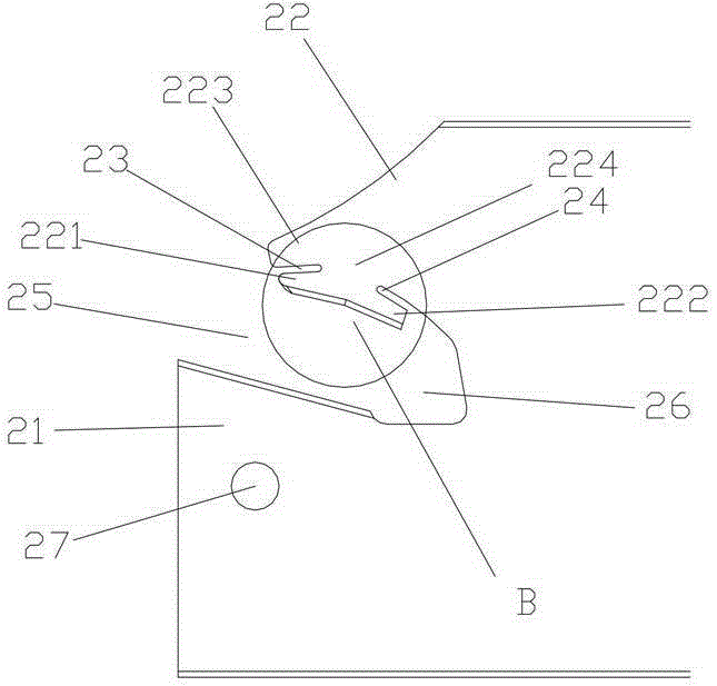
[0032] The cutter body 2 comprises a supporting part 21 and a clamping part 22; the clamping part 22 c...


PUM


Abstract

The invention relates to a grooving cutter which comprises a cutter blade and a cutter body, wherein the cutter body comprises a supporting part and a clamping part, and a cutter groove used for mounting and dismounting the cutter blade is arranged between the supporting part and the clamping part; the clamping part is provided with a clamping part front end, a clamping part limiting end and a clamping part rear end, the clamping part front end and the clamping part limiting end are separated through a front narrow groove, and the clamping part rear end is separated through a rear narrow groove; both the clamping part front end and the clamping part rear end have independent elasticity, and the clamping part limiting end is positioned above the clamping part front end. The grooving cutter has the advantages of being simple in structure, stable in clamping and high in supporting intensity and realizes multipoint clamping positioning.

Description

technical field [0001] The invention relates to the technical field of metal cutting, in particular to a grooving tool. Background technique [0002] In the metal cutting processing industry, the blade is subjected to a large cutting force during the cutting and grooving process, resulting in a large cutting vibration. Usually, the clamping of the blade by the tool is concentrated on the part of the blade near the cutting edge, so that the During the cutting process, the rear end of the blade vibrates greatly, the clamping reliability is not high, and the tool is prone to wear and deformation, which affects the machining accuracy of the part. [0003] U.S. Patent No. 6,234,727B1 discloses a cutting tool. The first clamping surface of the tool can elastically move around the first elastic axis of rotation, and the second clamping surface can elastically move around the second elastic axis of rotation. The first clamping surface is opposite to the blade. The upper front end o...

Claims


Application Information

Patent Timeline
Patent Type & Authority Applications(China)
IPC IPC(8): B23B27/16
CPCB23B27/1659B23B2205/02B23B2220/12
Inventor 王云志吴敏彭震王春秀杨红星
Owner ZHUZHOU CEMENTED CARBIDE CUTTING TOOLS CO LTD
Why Eureka
Try Eureka