
Feed cutter for feed puffing device

A technology of extruding device and feed, applied in feed, application, food science and other directions, can solve problems such as operator injury, cutter wear, easy aging, etc. handy effect

Inactive Publication Date: 2019-11-12
肥东县爱雯家庭农场
View PDF1 Cites 2 Cited by
  • Summary
  • Abstract
  • Description
  • Claims
  • Application Information

AI Technical Summary

Problems solved by technology

But it has the following disadvantages: (1) the cutter is installed on the cutter head through the inner hexagonal bolt. The friction of the parts in contact with the inner hexagon socket bolts can easily cause the hexagon socket bolts to loosen. The centrifugal force will cause the cutter to break away from the cutter head and be thrown out. cause injury; (2) the device is fixed to the cylindrical hole by the plastic sleeve of PVC hard engineering plastic to prevent the floating of the cutter, and heat energy will be generated during long-term high-speed rotation. Because of the poor thermal stability of PVC plastic, it is easy to be heated. Aging, so the plastic sleeve needs to be replaced frequently, which increases the cost of use

Method used


Image

  • Feed cutter for feed puffing device
  • Feed cutter for feed puffing device
  • Feed cutter for feed puffing device

Examples


Embodiment

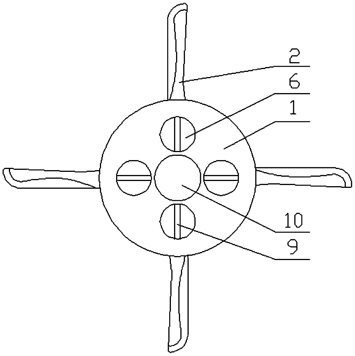
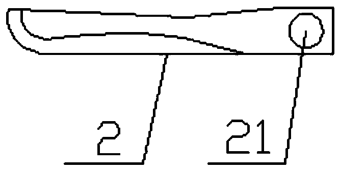
[0032] Such as figure 1 The shown feed cutter for a feed puffing device includes a circular cutter head 1 and at least two cutter heads 2 (generally four cutter heads 2) that are detachably mounted on the cutter head 1, such as figure 2 As shown, the mounting end of the cutter head 2 is provided with a mounting hole 21; Figure 5 and Figure 7 As shown in (a), the cutter head 1 includes an upper top plate 11 and a lower bottom plate 12 clamped on the upper and lower sides of the cutter head 2,

[0033] Combine below Figure 7 (b), Figure 7 (c), Figure 7 (d), Figure 8 and Picture 9 analysis,

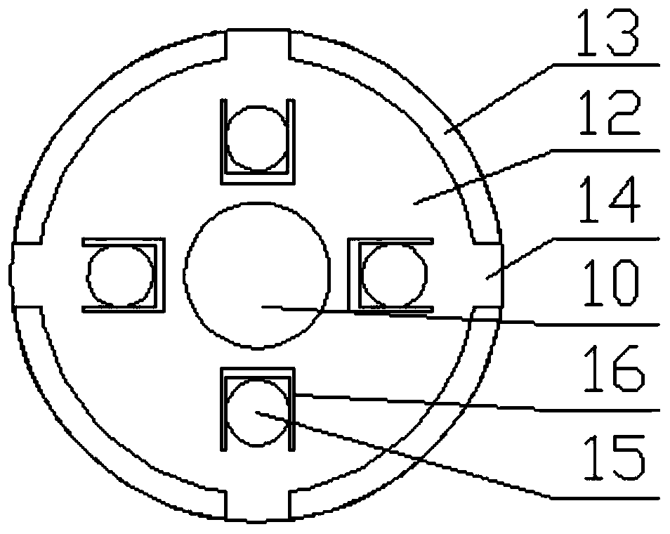
[0034] Such as image 3 As shown, the peripheral edge of the lower base plate 12 is evenly provided with side barriers 13 corresponding to the cutter head 2 one-to-one, and a socket 14 is formed between every two adjacent side barriers 13 for the cutter head 2 to insert. Such as Figure 5 As shown, the upper top plate 11 is fixed on the top of the side rail 13, as image 3 As shown, the u...


PUM


Abstract

The invention discloses a feed cutter for a feed puffing device, and belongs to the technical field of feed processing. The feed cutter includes a cutter disc and a cutter head detachably mounted on the cutter disc, a mounting hole is formed in the cutter head, the cutter disc includes an upper top plate and a lower top plate, and an inserting opening for inserting the cutter head is formed in theouter surface of the cutter disc; the upper top plate is provided with a circular inserting groove for vertically placing a clamping block, evenly arranged strip-shaped plates corresponding to the circumference of the mounting hole are hinged in the clamping block, the clamping block is connected with a rotating ring body in a threaded mode, an abutting block with an inner diameter gradually increasing from top to bottom is fixed into the rotating ring body, the top ends of the strip-shaped plates abut against the inner side of the abutting block, and a circular sealing block which can seal the circular inserting groove is fixed to the top of the rotating ring body. According to the feed cutter, associated locking assemblies do not generate accidentally reverse effects, and the cutter head is not prone to loosing; a plastic sleeve does not need to be used, the floating phenomenon of the cutter can be effectively prevented during rotating, it is not necessary to replace the plastic sleeve frequently, the use cost is greatly lowered, and manpower is saved; and operation is convenient, and materials are not prone to entering the knife disc.

Description

Technical field [0001] The invention relates to the technical field of feed processing, in particular to a feed cutter for a feed puffing device. Background technique [0002] The feed includes more than ten varieties of feed materials such as soybean, soybean meal, corn, fish meal, amino acids, miscellaneous meal, whey powder, oil, meat and bone meal, grains, feed additives, etc. After the feed raw materials are extruded, the flavor and palatability increase , It can stimulate the appetite of animals and is easier to digest, so the feed for animals will be processed by Penghua. Traditionally, in order to produce products of different specifications and material shapes in the extruded process, different specifications of feed cutters are needed to cut the feed. Because the cutter head and cutter head of the feed cutter are integrated, it is necessary to change the knife. The cutter heads are replaced together, resulting in a waste of resources. [0003] At present, in the patent ...

Claims


Application Information

Patent Timeline
Patent Type & Authority Applications(China)
IPC IPC(8): A23N17/00
CPCA23N17/00
Inventor 汤自凤
Owner 肥东县爱雯家庭农场
Learn More