Forging process for automobile part blank and forging equipment thereof
A technology for auto parts and blanks, applied in the field of forging, can solve problems such as poor spring absorption effect, affecting the quality of forgings, and damage to springs, and achieve good vibration reduction effects, good buffering effects, and guaranteed yields
- Summary
- Abstract
- Description
- Claims
- Application Information
AI Technical Summary
Problems solved by technology
Method used
Image
Examples
Embodiment 1
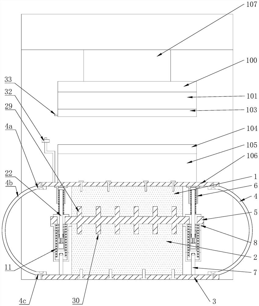
[0056] A forging equipment used in process S3, comprising a top plate 100, an upper die base 101, an upper die base 103, a lower die base 104, a lower die base 105, and a lower bottom plate 106, and the lower base plate 106 is fixed with a lower die base with a lower die base 104 105, the lower template 104 cooperates with the upper template 103, the upper template 103 is connected with the top plate 100 through the upper mold base 101, and the end of the top plate 100 is provided with a hydraulic drive device 107 with the top plate 100 reciprocating up and down, buffering and reducing The shock-absorbing base, the buffer and shock-absorbing base is fixedly arranged on the bottom of the lower base plate 106, and supports the lower base plate 106.
[0057] By setting the shock-absorbing buffer base, a good shock-absorbing effect can be achieved in the forging process, thereby ensuring the yield of parts and the stability of the equipment.
Embodiment 2
[0059] Further on the basis of Embodiment 1: the shock absorbing base includes
[0060] The upper shock-absorbing support seat 1, the lower bottom plate 106 is arranged on the upper end of the upper shock-absorbing support seat 1, and is fixed by bolts, and the cross-sectional area of the lower bottom plate 106 is larger than the cross-sectional area of the upper shock-absorbing support seat 1,
[0061] The lower shock-absorbing support seat 2 and the upper shock-absorbing support seat 1 are fixedly arranged at the lower end of the upper shock-absorbing support seat 1 to support the upper shock-absorbing support seat 1.
[0062] The lower support plate 3, the cross-sectional area of the lower support plate 3 is greater than the cross-sectional area of the lower shock-absorbing support seat 2, and the lower support plate 3 is arranged on the bottom of the lower shock-absorbing support seat 2, and is fixedly connected with the lower shock-absorbing support seat 2 by bolts...
Embodiment 3
[0068] Further on the basis of Embodiment 2: the upper shock-absorbing support seat 1 and the lower shock-absorbing support seat 2 are both made of buffer rubber, and several ribs 4 made of mild steel are evenly arranged on the lower bottom plate 106 and the support between the boards,
[0069] And the receiving rib 4 includes an upper receiving part 4c4a, an arc-shaped support part 4b and a lower receiving part 4c connected in sequence, the upper receiving part 4c4a is connected to the lower bottom plate 106, and the lower receiving part 4c is connected to the lower support plate 3, and the upper receiving part 4c4a and the lower receiving portion 4c are provided with connecting holes, and the connecting holes are provided with high-strength bolts,
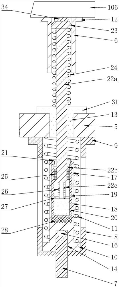
[0070] On the lower end surface of the lower bottom plate 106, a number of limit sleeves 6 corresponding to the upper ends of the limit support members and cooperating with the limit support members are fixedly arranged,
[0071...
PUM
 Abstract
Description
Claims
Application Information
 - R&D
- Intellectual Property
- Life Sciences
- Materials
- Tech Scout
- Unparalleled Data Quality
- Higher Quality Content
- 60% Fewer Hallucinations
Browse by: Latest US Patents, China's latest patents, Technical Efficacy Thesaurus, Application Domain, Technology Topic, Popular Technical Reports.
© 2025 PatSnap. All rights reserved.Legal|Privacy policy|Modern Slavery Act Transparency Statement|Sitemap|About US| Contact US: help@patsnap.com


